
Layer 3 design

 Layer 3 design 
5.1.6 This page will describe some Layer 3 design considerations.
A router is a Layer 3 device and is considered one of the most powerful devices in the network topology.
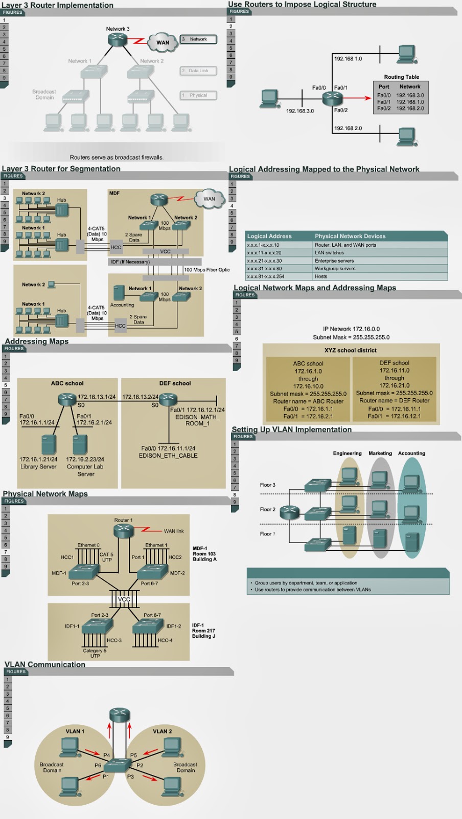
Layer 3 devices can be used to create unique LAN segments. Layer 3 devices allow communication between segments based on Layer 3 addresses, such as IP addresses. Implementation of Layer 3 devices allows for segmentation of the LAN into unique physical and logical networks. Routers also allow for connectivity to WANs, such as the Internet. 
Layer 3 routing determines traffic flow between unique physical network segments based on Layer 3 addresses. A router forwards data packets based on destination addresses. A router does not forward LAN-based broadcasts such as ARP requests. Therefore, the router interface is considered the entry and exit point of a broadcast domain and stops broadcasts to other LAN segments.
Routers provide scalability because they serve as firewalls for broadcasts and they can divide networks into subnetworks, or subnets, based on Layer 3 addresses. 
In order to decide whether to use routers or switches, it is important to determine the problem that needs to be solved. If the problem is related to protocol rather than issues of contention, then routers are the appropriate solution. Routers solve problems with excessive broadcasts, protocols that do not scale well, security issues, and network layer addresses. Routers are more expensive and more difficult to configure than switches.
Figure shows an example of an implementation that has multiple networks. All data traffic from Network 1 destined for Network 2 has to go through the router. In this implementation, there are two broadcast domains. The two networks have unique Layer 3 network address schemes. Multiple physical networks can be created if the horizontal cabling and vertical cabling are patched into the appropriate Layer 2 switch. This can be done with patch cables. This implementation also provides robust security because all traffic in and out of the LAN must pass through the router.
Once an IP address scheme is developed for a client, it should be clearly documented. A standard convention should be set for addresses of important hosts on the network. This address scheme should be kept consistent throughout the entire network. Address maps provide a snapshot of the network.   Physical maps of the network helps to troubleshoot the network. 
VLAN implementation combines Layer 2 switching and Layer 3 routing technologies to limit both collision domains and broadcast domains. VLANs also provide security with the creation of VLAN groups that communicate with other VLANs through routers. 
A physical port association is used to implement VLAN assignment. Ports P1, P4, and P6 have been assigned to VLAN 1. VLAN 2 has ports P2, P3, and P5. Communication between VLAN 1 and VLAN 2 can occur only through the router. This limits the size of the broadcast domains and uses the router to determine whether VLAN 1 can talk to VLAN 2. 
This page concludes this lesson. The next lesson will describe LAN switches. The first page describes the hierarchical design model.

Comments

Popular posts from this blog

OSI layers / Peer-to-peer communications / TCP/IP model

OSI layers 2.3.4 This page discusses the seven layers of the OSI model. The OSI reference model is a framework that is used to understand how information travels throughout a network. The OSI reference model explains how packets travel through the various layers to another device on a network, even if the sender and destination have different types of network media. In the OSI reference model, there are seven numbered layers, each of which illustrates a particular network function. - Dividing the network into seven layers provides the following advantages: • It breaks network communication into smaller, more manageable parts. • It standardizes network components to allow multiple vendor development and support. • It allows different types of network hardware and software to communicate with each other. • It prevents changes in one layer from affecting other layers. • It divides network communication into smaller parts to make learning it easier to understand. In the foll...

Advantages and disadvantages of link-state routing

Advantages and disadvantages of link-state routing 2.1.5  This page lists the advantages and disadvantages of link-state routing protocols. The following are advantages of link-state routing protocols:  Link-state protocols use cost metrics to choose paths through the network. The cost metric reflects the capacity of the links on those paths. Link-state protocols use triggered updates and LSA floods to immediately report changes in the network topology to all routers in the network. This leads to fast convergence times. Each router has a complete and synchronized picture of the network. Therefore, it is very difficult for routing loops to occur. Routers use the latest information to make the best routing decisions. The link-state database sizes can be minimized with careful network design. This leads to smaller Dijkstra calculations and faster convergence. Every router, at the very least, maps the topology of it...

Ports for services

Ports for services 10.2.2  Services running on hosts must have a port number assigned to them so communication can occur. A remote host attempting to connect to a service expects that service to use specific transport layer protocols and ports. Some ports, which are defined in RFC 1700, are known as the well-known ports. These ports are reserved in both TCP and UDP.  These well-known ports define applications that run above the transport layer protocols. For example, a server that runs FTP will use ports 20 and 21 to forward TCP connections from clients to its FTP application. This allows the server to determine which service a client requests. TCP and UDP use port numbers to determine the correct service to which requests are forwarded. The next page will discuss ports in greater detail.