
Configuring RIP v2

Configuring RIP v2
1.2.4 This page will teach students how to configure RIP v2. RIP v2 is a dynamic routing protocol that is configured by naming the routing protocol RIP Version 2, and then assigning IP network numbers without specifying subnet values. This section describes the basic commands used to configure RIP v2 on a Cisco router. 
To enable a dynamic routing protocol, the following tasks must be completed:
  • Select a routing protocol, such as RIP v2.
  • Assign the IP network numbers without specifying the subnet values.
  • Assign the network or subnet addresses and the appropriate subnet mask to the interfaces.
RIP v2 uses multicasts to communicate with other routers. The routing metric helps the routers find the best path to each network or subnet.
The router command starts the routing process. The network command causes the implementation of the following three functions:
  • The routing updates are multicast out an interface.
  • The routing updates are processed if they enter that same interface.
  • The subnet that is directly connected to that interface is advertised.
The network command is required because it allows the routing process to determine which interfaces will participate in the sending and receiving of routing updates. The network command starts up the routing protocol on all interfaces that the router has in the specified network. The network command also allows the router to advertise that network.
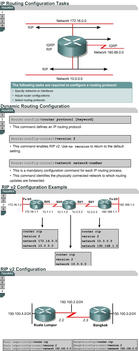
The router rip and version 2 commands combined specify RIP v2 as the routing protocol, while the network command identifies a participating attached network. 
In this example, the configuration of Router A includes the following:
  • router rip – Enables RIP as the routing protocol
  • version 2 – Identifies version 2 as the version of RIP being used
  • network 172.16.0.0 – Specifies a directly connected network
  • network 10.0.0.0 – Specifies a directly connected network
The interfaces on Router A connected to networks 172.16.0.0 and 10.0.0.0, or their subnets, will send and receive RIP v2 updates. These routing updates allow the router to learn the network topology. Routers B and C have similar RIP configurations but with different network numbers specified.
Figure shows another example of a RIP v2 configuration.
The Lab Activities on this page will show students how to convert RIP v1 to RIP v2.
The next page will describe the commands that are used to verify RIP v2

Comments

Popular posts from this blog

OSI layers / Peer-to-peer communications / TCP/IP model

OSI layers 2.3.4 This page discusses the seven layers of the OSI model. The OSI reference model is a framework that is used to understand how information travels throughout a network. The OSI reference model explains how packets travel through the various layers to another device on a network, even if the sender and destination have different types of network media. In the OSI reference model, there are seven numbered layers, each of which illustrates a particular network function. - Dividing the network into seven layers provides the following advantages: • It breaks network communication into smaller, more manageable parts. • It standardizes network components to allow multiple vendor development and support. • It allows different types of network hardware and software to communicate with each other. • It prevents changes in one layer from affecting other layers. • It divides network communication into smaller parts to make learning it easier to understand. In the foll...

Advantages and disadvantages of link-state routing

Advantages and disadvantages of link-state routing 2.1.5  This page lists the advantages and disadvantages of link-state routing protocols. The following are advantages of link-state routing protocols:  Link-state protocols use cost metrics to choose paths through the network. The cost metric reflects the capacity of the links on those paths. Link-state protocols use triggered updates and LSA floods to immediately report changes in the network topology to all routers in the network. This leads to fast convergence times. Each router has a complete and synchronized picture of the network. Therefore, it is very difficult for routing loops to occur. Routers use the latest information to make the best routing decisions. The link-state database sizes can be minimized with careful network design. This leads to smaller Dijkstra calculations and faster convergence. Every router, at the very least, maps the topology of it...

Ports for services

Ports for services 10.2.2  Services running on hosts must have a port number assigned to them so communication can occur. A remote host attempting to connect to a service expects that service to use specific transport layer protocols and ports. Some ports, which are defined in RFC 1700, are known as the well-known ports. These ports are reserved in both TCP and UDP.  These well-known ports define applications that run above the transport layer protocols. For example, a server that runs FTP will use ports 20 and 21 to forward TCP connections from clients to its FTP application. This allows the server to determine which service a client requests. TCP and UDP use port numbers to determine the correct service to which requests are forwarded. The next page will discuss ports in greater detail.