100BASE-TX
7.1.7 This page will describe 100BASE-TX.
In 1995, 100BASE-TX was the standard, using Category 5 UTP cable, which became commercially successful.
The original coaxial Ethernet used half-duplex transmission so only one device could transmit at a time. In 1997, Ethernet was expanded to include a full-duplex capability that allowed more than one PC on a network to transmit at the same time. Switches replaced hubs in many networks. These switches had full-duplex capabilities and could handle Ethernet frames quickly.
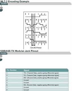
100BASE-TX uses 4B/5B encoding, which is then scrambled and converted to Multi-Level Transmit (MLT-3) encoding. Figure shows four waveform examples. The top waveform has no transition in the center of the timing window. No transition indicates a binary zero. The second waveform shows a transition in the center of the timing window. A transition represents a binary one. The third waveform shows an alternating binary sequence. The fourth wavelength shows that signal changes indicate ones and horizontal lines indicate zeros.
Figure shows the pinout for a 100BASE-TX connection. Notice that the two separate transmit-receive paths exist. This is identical to the 10BASE-T configuration.
100BASE-TX carries 100 Mbps of traffic in half-duplex mode. In full-duplex mode, 100BASE-TX can exchange 200 Mbps of traffic. The concept of full duplex will become more important as Ethernet speeds increase.
100BASE-FX
7.1.8 This page covers 100BASE-FX.
When copper-based Fast Ethernet was introduced, a fiber version was also desired. A fiber version could be used for backbone applications, connections between floors, buildings where copper is less desirable, and also in high-noise environments. 100BASE-FX was introduced to satisfy this desire. However, 100BASE-FX was never adopted successfully. This was due to the introduction of Gigabit Ethernet copper and fiber standards. Gigabit Ethernet standards are now the dominant technology for backbone installations, high-speed cross-connects, and general infrastructure needs.
The timing, frame format, and transmission are the same in both versions of 100-Mbps Fast Ethernet. In Figure , the top waveform has no transition, which indicates a binary 0. In the second waveform, the transition in the center of the timing window indicates a binary 1. In the third waveform, there is an alternating binary sequence. In the third and fourth waveforms it is more obvious that no transition indicates a binary zero and the presence of a transition is a binary one.
Figure summarizes a 100BASE-FX link and pinouts. A fiber pair with either ST or SC connectors is most commonly used.
The separate Transmit (Tx) and Receive (Rx) paths in 100BASE-FX optical fiber allow for 200-Mbps transmission.
The next page will explain the Fast Ethernet architecture.


Comments
Post a Comment