Sunday, November 11, 2012

Verifying RIP v2

Verifying RIP v2

1.2.5 The show ip protocols and show ip route commands display information about routing protocols and the routing table. This page explains how show commands are used to verify a RIP configuration.
The show ip protocols command displays values about routing protocols and routing protocol timer information associated with the router. In the example, the router is configured with RIP and sends updated routing table information every 30 seconds. This interval is configurable. If a router running RIP does not receive an update from another router for 180 seconds or more, the first router marks the routes served by the non-updating router as being invalid. The holddown timer is set to 180 seconds. Therefore, an update to a route that was down and is now up could stay in the holddown state until the full 180 seconds have passed.
If there is still no update after 240 seconds the router removes the routing table entries. The router is injecting routes for the networks listed following the Routing for Networks line. The router is receiving routes from the neighboring RIP routers listed following the Routing Information Sources line. The distance default of 120 refers to the administrative distance for a RIP route.
The show ip interface brief command can also be used to list a summary of the information and status of an interface.
The show ip route command displays the contents of the IP routing table. The routing table contains entries for all known networks and subnetworks, and contains a code that indicates how that information was learned.
Examine the output to see if the routing table is populated with routing information. If entries are missing, routing information is not being exchanged. Use the show running-config or show ip protocols Privileged EXEC commands on the router to check for a possible misconfigured routing protocol.
The Lab Activity will teach students how to use show commands to verify RIP v2 configurations.
The next page will discuss the debug ip rip command.
Configuring RIP v2

Configuring RIP v2
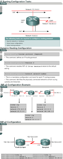
1.2.4 This page will teach students how to configure RIP v2. RIP v2 is a dynamic routing protocol that is configured by naming the routing protocol RIP Version 2, and then assigning IP network numbers without specifying subnet values. This section describes the basic commands used to configure RIP v2 on a Cisco router. 
To enable a dynamic routing protocol, the following tasks must be completed:
  • Select a routing protocol, such as RIP v2.
  • Assign the IP network numbers without specifying the subnet values.
  • Assign the network or subnet addresses and the appropriate subnet mask to the interfaces.
RIP v2 uses multicasts to communicate with other routers. The routing metric helps the routers find the best path to each network or subnet.
The router command starts the routing process. The network command causes the implementation of the following three functions:
  • The routing updates are multicast out an interface.
  • The routing updates are processed if they enter that same interface.
  • The subnet that is directly connected to that interface is advertised.
The network command is required because it allows the routing process to determine which interfaces will participate in the sending and receiving of routing updates. The network command starts up the routing protocol on all interfaces that the router has in the specified network. The network command also allows the router to advertise that network.
The router rip and version 2 commands combined specify RIP v2 as the routing protocol, while the network command identifies a participating attached network. 
In this example, the configuration of Router A includes the following:
  • router rip – Enables RIP as the routing protocol
  • version 2 – Identifies version 2 as the version of RIP being used
  • network 172.16.0.0 – Specifies a directly connected network
  • network 10.0.0.0 – Specifies a directly connected network
The interfaces on Router A connected to networks 172.16.0.0 and 10.0.0.0, or their subnets, will send and receive RIP v2 updates. These routing updates allow the router to learn the network topology. Routers B and C have similar RIP configurations but with different network numbers specified.
Figure shows another example of a RIP v2 configuration.
The Lab Activities on this page will show students how to convert RIP v1 to RIP v2.
The next page will describe the commands that are used to verify RIP v2

Comparing RIP v1 and v2

Comparing RIP v1 and v2
1.2.3 This page will provide some more information about how RIP works. It will also describe the differences between RIP v1 and RIP v2. RIP uses distance vector algorithms to determine the direction and distance to any link in the internetwork. If there are multiple paths to a destination, RIP selects the path with the least number of hops. However, because hop count is the only routing metric used by RIP, it does not necessarily select the fastest path to a destination.
RIP v1 allows routers to update their routing tables at programmable intervals. The default interval is 30 seconds. The continual sending of routing updates by RIP v1 means that network traffic builds up quickly.  To prevent a packet from looping infinitely, RIP allows a maximum hop count of 15. If the destination network is more than 15 routers away, the network is considered unreachable and the packet is dropped. This situation creates a scalability issue when routing in large heterogeneous networks. RIP v1 uses split horizon to prevent loops. This means that RIP v1 advertises routes out an interface only if the routes were not learned from updates entering that interface. It uses holddown timers to prevent routing loops. Holddowns ignore any new information about a subnet indicating a poorer metric for a time equal to the holddown timer.
Figure summarizes the behavior of RIP v1 when used by a router.
RIP v2 is an improved version of RIP v1. It has many of the same features of RIP v1. RIP v2 is also a distance vector protocol that uses hop count, holddown timers, and split horizon. Figure compares and contrasts RIP v1 and RIP v2. The TTL field in the IP packet forces the packet to be dropped. When the hop count reaches 15 routers, the network is considered unreachable, and the packet is dropped because the router doesn't have a route to the destination network.
The first Lab Activity on this page will show students how to set up and configure RIP on routers. The second Lab Activity will review the basic configuration of routers. The Interactive Media Activity will help students understand the differences between RIP v1 and RIP v2.
The next page will explain how RIP v2 is configured.

RIP v2 feature

RIP v2 feature
1.2.2 This page will discuss RIP v2, which is an improved version of RIP v1. Both versions of RIP share the following features:
  • It is a distance vector protocol that uses a hop count metric.
  • It uses holddown timers to prevent routing loops – default is 180 seconds.
  • It uses split horizon to prevent routing loops.
  • It uses 16 hops as a metric for infinite distance.
RIP v2 provides prefix routing, which allows it to send out subnet mask information with the route update. Therefore, RIP v2 supports the use of classless routing in which different subnets within the same network can use different subnet masks, as in VLSM.
RIP v2 provides for authentication in its updates. A set of keys can be used on an interface as an authentication check. RIP v2 allows for a choice of the type of authentication to be used in RIP v2 packets. The choice can be either clear text or Message-Digest 5 (MD5) encryption. Clear text is the default. MD5 can be used to authenticate the source of a routing update. MD5 is typically used to encrypt enable secret passwords and it has no known reversal.
RIP v2 multicasts routing updates using the Class D address 224.0.0.9, which provides for better efficiency.
The next page will discuss RIP in greater detail.

RIP Version 2 (RIP history)


RIP Version 2

RIP history
1.2.1 

This page will explain the functions and limitations of RIP. The Internet is a collection of autonomous systems (AS). Each AS is generally administered by a single entity. Each AS has a routing technology which can differ from other autonomous systems. The routing protocol used within an AS is referred to as an Interior Gateway Protocol (IGP). A separate protocol used to transfer routing information between autonomous systems is referred to as an Exterior Gateway Protocol (EGP). RIP is designed to work as an IGP in a moderate-sized AS. It is not intended for use in more complex environments.
RIP v1 is considered a classful IGP. RIP v1 is a distance vector protocol that broadcasts the entire routing table to each neighbor router at predetermined intervals. The default interval is 30 seconds. RIP uses hop count as a metric, with 15 as the maximum number of hops.
If the router receives information about a network, and the receiving interface belongs to the same network but is on a different subnet, the router applies the one subnet mask that is configured on the receiving interface:
  • For Class A addresses, the default classful mask is 255.0.0.0.
  • For Class B addresses, the default classful mask is 255.255.0.0.
  • For Class C addresses, the default classful mask is 255.255.255.0.
RIP v1 is a popular routing protocol because virtually all IP routers support it. The popularity of RIP v1 is based on the simplicity and the universal compatibility it demonstrates. RIP v1 is capable of load balancing over as many as six equal-cost paths, with four paths as the default.
RIP v1 has the following limitations:
  • It does not send subnet mask information in its updates.
  • It sends updates as broadcasts on 255.255.255.255.
  • It does not support authentication.
  • It is not able to support VLSM or classless interdomain routing (CIDR).
RIP v1 is simple to configure, as shown in Figure .
The next page will introduce RIP v2.

RIP Version 2 (


Saturday, November 10, 2012

Configuring VLSM


Configuring VLSM
1.1.6 This page will teach students how to calculate and configure VLSM. If VLSM is the scheme chosen, it must then be calculated and configured correctly. 
The following are VLSM calculations for the LAN connections in Figure :
  • Network address: 192.168.10.0
  • The Perth router has to support 60 hosts. That means a minimum of six bits are needed in the host portion of the address. Six bits will yield 26 – 2, or 62 possible host addresses. The LAN connection for the Perth router is assigned the 192.168.10.0/26 subnet.
  • The Sydney and Singapore routers have to support 12 hosts each. That means a minimum of four bits are needed in the host portion of the address. Four bits will yield 24 – 2, or 14 possible host addresses. The LAN connection for the Sydney router is assigned the 192.168.10.96/28 subnet and the LAN connection for the Singapore router is assigned the 192.168.10.112/28 subnet.
  • The KL router has to support 28 hosts. That means a minimum of five bits are needed in the host portion of the address. Five bits will yield 25 – 2, or 30 possible host addresses. The LAN connection for the KL router is assigned the 192.168.10.64/27 subnet.
The following are VLSM calculations for the point-to-point connections in Figure :
  • Perth to KL
The connection from Perth to KL requires only two host addresses. That means a minimum of two bits are needed in the host portion of the address. Two bits will yield 22 – 2, or 2 possible host addresses. The Perth to KL connection is assigned the 192.168.10.128/30 subnet.
  • Sydney to KL
The connection from Sydney to KL requires only two host addresses. That means a minimum of two bits are needed in the host portion of the address. Two bits will yield 22 – 2, or 2 possible host addresses. The Sydney to KL connection is assigned the 192.168.10.132/30 subnet.
  • Singapore to KL
The connection from Singapore to KL requires only two host addresses. That means a minimum of two bits are needed in the host portion of the address. Two bits will yield 22 – 2, or 2 possible host addresses. The Singapore to KL connection is assigned the 192.168.10.136/30 subnet.
The following configuration is for the Singapore to KL point-to-point connection: 
Singapore(config)#interface serial 0
Singapore(config-if)#ip address 192.168.10.137 255.255.255.252
KualaLumpur(config)#interface serial 1
KualaLumpur(config-if)#ip address 192.168.10.138 255.255.255.252
This page concludes this lesson. The next lesson will discuss RIP. The first page describes RIP v1.