Sunday, August 14, 2016

1.1.2 Introducing NAT and PAT


1.1.2 Introducing NAT and PAT

NAT is designed to conserve IP addresses and enable networks to use private IP addresses on internal networks. These private, internal addresses are translated to routable, public addresses. This is accomplished by internetwork devices running specialized NAT software which can increase network privacy by hiding internal IP addresses.
A NAT enabled device typically operates at the border of a stub network. A stub network is a network that has a single connection to its neighbor network. When a host inside the stub network wants to transmit to a host on the outside, it forwards the packet to the border gateway router. The border gateway router performs the NAT process, translating the internal private address of a host to a public, external routable address. In NAT terminology, the internal network is the set of networks that are subject to translation. The external network refers to all other addresses.
Cisco defines the following NAT terms:
  • Inside local address – The IP address assigned to a host on the inside network. The address is usually not an IP address assigned by the Internet Network Information Center (InterNIC) or service provider. This address is likely to be an RFC 1918 private address.
  • Inside global address – A legitimate IP address assigned by the InterNIC or service provider that represents one or more inside local IP addresses to the outside world.
  • Outside local address – The IP address of an outside host as it is known to the hosts on the inside network.
Outside global address – The IP address assigned to a host on the outside network. The owner of the host assigns this address.

Module 1: Scaling IP Addresses / Private addressing

Module 1: Scaling IP Addresses
1.1.1 Private Addressing
RFC 1918 sets aside the following three blocks of private IP addresses:
  • 1 Class A address
  • 16 Class B addresses
  • 256 Class C addresses
These addresses are for private, internal network use only. Packets containing these addresses are not routed over the Internet.
Public Internet addresses must be registered by a company with an Internet authority, for example, American Registry for Internet Numbers (ARIN) or Réseaux IP Européens (RIPE), the Regional Internet Registry responsible for Europe and North Africa. These public Internet addresses can also be leased from an ISP. Private IP addresses are reserved and can be used by anyone. That means two networks, or two million networks, can each use the same private address. A router should never route RFC 1918 addresses. ISPs typically configure the border routers to prevent privately addressed traffic from being forwarded.
NAT provides great benefits to individual companies and the Internet. Before NAT, a host with a private address could not access the Internet. Using NAT, individual companies can address some or all of their hosts with private addresses and use NAT to provide access to the Internet.

Thursday, April 17, 2014

Module 7 : Summary

Summary
This page summarizes the topics discussed in this module.
Redundancy is defined as a duplication of components that allows continued functionality despite the failure of an individual component. In a network, redundancy means to have a backup method to connect all devices. Redundant topologies increase network reliability and decrease downtime caused by a single point of failure.
A redundant switched topology may cause broadcast storms, multiple frame transmissions, and MAC address table instability problems. A broadcast storm is caused by multiple hosts that send and receive multiple broadcast messages. The result is that they continue to propagate broadcast traffic over and over until one of the switches is disconnected. During a broadcast storm, the network appears to be down or extremely slow. Multiple frame transmissions occur when a router receives multiple copies of a frame from multiple switches due to an unknown MAC address. These excessive transmissions cause the router to time out. When a switch incorrectly learns a MAC address of a port, it can cause a loop situation and instability for the MAC address table.
Since switches operate at Layer 2 of the OSI model, all forwarding decisions are made at this level. Layer 2 does not provide a TTL value, which is the set amount of time a packet is provided to reach a destination. The problem is that physical topologies contain switching or bridging loops necessary for reliability, yet a switched network cannot have loops. The solution is to allow physical loops, but create a loop free logical topology.
The loop free logical topology created is called a tree. The topology is a star or extended star that spans the tree of the network. All devices are reachable or spanned. The algorithm used to create this loop free logical topology is the spanning-tree algorithm.
The Spanning-Tree Protocol establishes a root node, called the root bridge. The Spanning-Tree Protocol constructs a topology that has one path for every node on the network. This results in a tree that originates from the root bridge. Redundant links that are not part of the shortest path tree are blocked. It is because certain paths are blocked that a loop free topology is possible. Data frames received on blocked links are dropped.
Switches send messages called the bridge protocol data units (BPDUs) to allow the formation of a loop free logical topology. BPDUs continue to be received on blocked ports. BPDUs contain information that allow switches to perform specific actions:
  • Select a single switch that will act as the root of the spanning-tree.
  • Calculate the shortest path from itself to the root switch.
  • Designate one of the switches as the designated switch.
  • Choose one of its ports as its root port, for each non-root switch.
  • Select ports that are part of the spanning-tree. These ports are called designated ports.
IEEE 802.1w LAN standard defines the Rapid Spanning-Tree Protocol. It serves to clarify port states and roles, define a set of link types, and allow switches in a converged network to generate BPDUs rather than use the root bridge BPDUs. The blocking state of a port is renamed as the discarding state. The role of a discarding port is that of an alternate port. The discarding port can become the designated port if the designated port of the segment fails.

Spanning-tree recalculation / Rapid spanning-tree protocol

Spanning-tree recalculation
7.2.6 This page will describe the convergence of a spanning-tree network.
A switched internetwork has converged when all the switch and bridge ports are in either the forwarding or blocking state. Forwarding ports send and receive data traffic and BPDUs. Blocking ports only receive BPDUs.
When the network topology changes, switches and bridges recompute the spanning-tree and cause a disruption in network traffic.  
Convergence on a new spanning-tree topology that uses the IEEE 802.1d standard can take up to 50 seconds. This convergence is made up of the max-age of 20 seconds, plus the listening forward delay of 15 seconds, and the learning forward delay of 15 seconds.
The Lab Activities will show students how to create and verify a basic switch configuration.
The next page will introduce the Rapid Spanning-Tree Protocol.


Rapid spanning-tree protocol
7.2.7 This page will describe the Rapid Spanning-Tree Protocol.
The Rapid Spanning-Tree Protocol is defined in the IEEE 802.1w LAN standard. The standard and protocol introduce new features:
  • Clarification of port states and roles
  • Definition of a set of link types that can go to forwarding state rapidly
  • Concept of allowing switches in a converged network to generate BPDUs rather than relaying root bridge BPDUs
The blocking state of a port is renamed as the discarding state. The role of a discarding port is that of an alternate port. The discarding port can become the designated port if the designated port of the segment fails.
Link types have been defined as point-to-point, edge-type, and shared. These changes allow rapid discovery of link failure in switched networks.
Point-to-point links and edge-type links can go to the forwarding state immediately.
Network convergence should take no longer than 15 seconds with these changes.
The Rapid Spanning-Tree Protocol, IEEE 802.1w, will eventually replace the Spanning-Tree Protocol, IEEE 802.1d.
This page concludes this lesson. The next page will summarize the main points from this module.

Selecting the root bridge / Stages of spanning-tree port states

Selecting the root bridge
7.2.4 This page will explain how a root bridge is selected in an STP network.
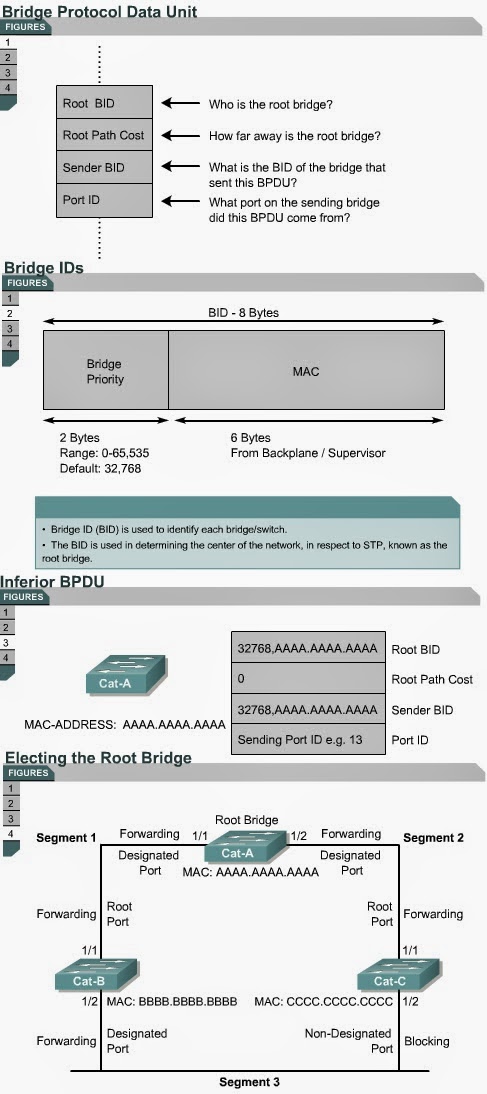
The first decision that all switches in the network make, is to identify the root bridge. The position of the root bridge in a network affects the traffic flow.
When a switch is turned on, the spanning-tree algorithm is used to identify the root bridge. BPDUs are sent out with the bridge ID (BID). The BID consists of a bridge priority that defaults to 32768 and the switch MAC address. By default BPDUs are sent every two seconds.
When a switch first starts up, it assumes it is the root switch and sends BPDUs that contain the switch MAC address in both the root and sender BID. These BPDUs are considered inferior because they are generated from the designated switch that has lost its link to the root bridge. The designated switch transmits the BPDUs with the information that it is the root bridge as well as the designated bridge. These BPDUs contain the switch MAC address in both the root and sender BID. The BIDs are received by all switches. Each switch replaces higher root BIDs with lower root BIDs in the BPDUs that are sent out. All switches receive the BPDUs and determine that the switch with the lowest root BID value will be the root bridge.  Network administrators can set the switch priority to a smaller value than the default, which makes the BID smaller. This should only be implemented when the traffic flow on the network is well understood. The Lab Activities will teach students how to select the root bridge for a basic switch configuration. The next page will discuss the STP port states.


Stages of spanning-tree port states
7.2.5 This page will explain the five port states of a switch that uses STP.
Time is required for protocol information to propagate throughout a switched network. Topology changes in one part of a network are not instantly known in other parts of the network due to propagation delay. Data loops can occur when a switch changes the state of a port too quickly.
Each port on a switch that uses the Spanning-Tree Protocol has one of five states, as shown in Figure .
In the blocking state, ports can only receive BPDUs. Data frames are discarded and no addresses can be learned. It may take up to 20 seconds to change from this state.
Ports transition from the blocking state to the listening state. In this state, switches determine if there are any other paths to the root bridge. The path that is not the least cost path to the root bridge returns to the blocking state. The listening period is called the forward delay and lasts for 15 seconds. In the listening state, data is not forwarded and MAC addresses are not learned. BPDUs are still processed.
Ports transition from the listening state to the learning state. In this state, data is not forwarded, but MAC addresses are learned from traffic that is received. The learning state lasts for 15 seconds and is also called the forward delay. BPDUs are still processed.
Ports transitions from the learning state to the forwarding state. In this state user data is forwarded and MAC addresses continue to be learned. BPDUs are still processed.
A port can be in a disabled state. This disabled state can occur when an administrator shuts down the port or the port fails.
The time values given for each state are the default values. These values have been calculated on an assumption that there will be a maximum of seven switches in any branch of the spanning-tree from the root bridge.
The Interactive Media Activities will help students learn the five spanning-tree port states.

STP

Spanning Tree Protocol
7.2.3 This page will teach students about the ports and devices that are found in an STP switched network.
When the network has stabilized, it has converged and there is one spanning-tree per network.
As a result, for every switched network the following elements exist:
  • One root bridge per network
  • One root port per non-root bridge
  • One designated port per segment
  • Unused, or non-designated ports
Root ports and designated ports are used for forwarding (F) data traffic.
Non-designated ports discard data traffic. These ports are called blocking (B) or discarding ports. 
The next page will discuss the root bridge. 

Spanning Tree Protocol

Spanning Tree Protocol
7.2.2 This page will explain how STP can be used to create a loop free network.
Ethernet bridges and switches can implement the IEEE 802.1d Spanning-Tree Protocol and use the spanning-tree algorithm to construct a loop free shortest path network. 
Shortest path is based on cumulative link costs. Link costs are based on the speed of the link. 
The Spanning-Tree Protocol establishes a root node called the root bridge. The Spanning-Tree Protocol constructs a topology that has one path for every node on the network. This tree originates from the root bridge. Redundant links that are not part of the shortest path tree are blocked.
It is because certain paths are blocked that a loop free topology is possible. Data frames received on blocked links are dropped.
The Spanning-Tree Protocol requires network devices to exchange messages to detect bridging loops. Links that will cause a loop are put into a blocking state.
Switches send messages called the bridge protocol data units (BPDUs) to allow the formation of a loop free logical topology. BPDUs continue to be received on blocked ports. This ensures that if an active path or device fails, a new spanning-tree can be calculated.
BPDUs contain information that allow switches to perform specific actions:
  • Select a single switch that will act as the root of the spanning-tree.
  • Calculate the shortest path from itself to the root switch.
  • Designate one of the switches as the closest one to the root, for each LAN segment. This switch is called the designated switch. The designated switch handles all communication from that LAN segment towards the root bridge.
  • Choose one of its ports as its root port, for each non-root switch. This is the interface that gives the best path to the root switch.
  • Select ports that are part of the spanning-tree. These ports are called designated ports. Non-designated ports are blocked. 
The Interactive Media Activity will teach students about STP.
The next page will describe the features of a spanning-tree network.