Saturday, October 22, 2011

Troubleshooting routing issues

Troubleshooting routing issues 
9.3.5 This page will describe the show ip protocols and show ip route commands. These commands display information about routing protocols and the routing table. The output from these commands can be used to verify the routing protocol configuration.
The show ip route command may be the most important command used to troubleshoot routing issues. This command displays the contents of the IP routing table. The output from the show ip route command shows the entries for all known networks and subnetworks, and how that information was learned. 
If there is a problem reaching a host in a particular network, then the output of the show ip route command can be used to verify that the router has a route to that network.
If the output of the show ip route command does not show the expected learned routes, or any learned routes, then the problem may be that routing information has not been exchanged. In this case, use the show ip protocols command on the router to check for a routing protocol configuration error.
The show ip protocols command displays values about IP routing protocol information on the entire router. This command can be used to confirm which protocols are configured, which networks are being advertised, which interfaces are sending updates, and the sources of routing updates. The show ip protocols output also shows timers, filters, route summarization, route redistribution, and other parameters that are specific to each routing protocol that is enabled on the router. When multiple routing protocols are configured, the information about each protocol is listed in a separate section. 
The show ip protocols command output can be used to diagnose many routing issues. For example, it can be used to identify a router that may advertise incorrect routing information. This command may be used to confirm that expected protocols, advertised networks, and routing neighbors are present. It is important to have documentation that indicates the expected results, or baseline information, when a problem occurs. It may be impossible to identify the problem without such documentation.
The Lab Activity will teach students how to use the show ip route and show ip protocols command.
The next page will discuss the show controllers serial command.

Troubleshooting using show cdp / traceroute

Troubleshooting using show cdp 
9.3.3 This page will explain the functions of the show cdp command.
CDP advertises device information to its direct neighbors. This includes MAC and IP addresses and outgoing interfaces.
The output from the show cdp neighbors command displays information about directly connected Cisco device neighbors. This information is useful for debugging connectivity issues. If a cabling problem is suspected, enable the interfaces with the no shutdown command and then execute the show cdp neighbors detail command before any other configuration. The command displays specific device detail such as the active interfaces, the port ID, and the device. The version of Cisco IOS that is running on the remote devices is also shown.
If the physical layer functions properly, then all other directly connected Cisco devices should be displayed. If no known device appears, this usually indicates a Layer 1 problem.
One area of concern with CDP is security. The amount of information CDP provides is so extensive that it can be a potential security hole. For security reasons CDP should be configured only on links between Cisco devices and disabled on user ports or links that are not locally managed.
In the Lab Activity, students will use the show cdp command to learn about network devices.
The next page will discuss the traceroute command.
Troubleshooting using show traceroute
9.3.4  This page will describe the functions of the traceroute command.
The traceroute command is often referred to as the trace command in reference materials. However, the correct command syntax is traceroute. The traceroute command displays the routes that packets take to their destinations. The traceroute command can also be used to test each hop at the network layer and provide performance benchmarks.
The output of the traceroute command generates a list of hops that were successfully reached.  If the data successfully reaches the intended destination, then the output indicates every router that the datagram passes through. This output can be captured and used for future troubleshooting of the internetwork.
Traceroute output will also indicate the specific hop at which the failure occurs. A line of output is generated on the terminal for each router in the path. This indicates the IP address of the interface that the data entered. If an asterisk (*) appears, the packet failed. To isolate the problem area, obtain the last good hop from the traceroute output and compare it to a diagram of the internetwork.
The traceroute command also provides information about the performance of links. The round trip time (RTT) is the time required to send an echo packet and get a response. This is useful for an approximate idea of the delay on the link. These figures are not precise enough to be used for an accurate performance evaluation. However, this output can be captured and used for future performance troubleshooting of the internetwork.
Notice that the device receiving the traceroute also has to know how to send the reply back to the source of the traceroute. For the traceroute or ping data to make the round trip between routers, there must be known routes in both directions. A failed response is not always an indication of a problem because ICMP messages could be rate-limited or filtered at the host site. This is especially true across the Internet.
Traceroute sends out a sequence of User Datagram Protocol (UDP) datagrams from the router to an invalid port address on the remote host. For the first sequence of three datagrams, a TTL field value is set to 1. The TTL value of 1 causes the datagram to time out at the first router in the path. This router then responds with an ICMP Time Exceeded Message (TEM) indicating that the datagram has expired.
Three more UDP messages are now sent, this time with the TTL value set to 2. This causes the second router to return ICMP TEMs. This process continues until the packets actually reach the other destination or the maximum TTL has been reached. The default maximum TTL for traceroute is 30.
Since these datagrams are trying to access an invalid port at the destination host, ICMP Port Unreachable Messages are returned instead of ICMP TEMs. This indicates an unreachable port and signals the Traceroute program to end the process.
The Lab Activity will help students become more familiar with the traceroute command.
The next page will discuss some other commands that are used to troubleshoot routing issues.

Troubleshooting Layer 2 using show interfaces

Troubleshooting Layer 2 using show interfaces 
9.3.2 This page will further explain why the show interfaces command may be the most important tool to discover Layer 1 and Layer 2 problems with the router. The first parameter, which is line, refers to the physical layer. The second parameter, which is protocol, indicates if the IOS processes that control the line protocol consider the interface usable. This is determined by whether keepalives are successfully received. Keepalives are defined as messages sent by one network device to inform another network device that the virtual circuit between the two is still active. If the interface misses three consecutive keepalives, the line protocol is marked as down.
When the line is down, the protocol is always down, because there is no useable media for the Layer 2 protocol. This will be true when the interface is down due to a hardware problem and when it is administratively down.
If the interface is up and the line protocol is down, a Layer 2 problem exists. Possible causes are as follows:
  • No keepalives
  • No clock rate
  • Mismatch in encapsulation type
The show interfaces command should be used after configuring a serial interface to verify the changes and that the interface is operational.
The Interactive Media activity will help students understand the show interfaces command.
The next page will discuss the show cdp command

Troubleshooting Layer 1 using show interfaces


Troubleshooting Layer 1 using show interfaces 
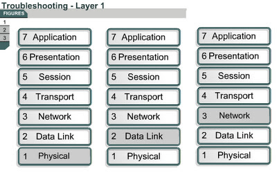
9.3.1 This page will discuss show commands and explain how they are used to troubleshoot Layer 1 issues.
The Cisco IOS contains many commands for troubleshooting. Among the more widely used are the show commands. Every aspect of the router can be viewed with one or more of the show commands. The show command used to check the status and statistics of the interfaces is the show interfaces command. The show interfaces command without arguments returns status and statistics on all the router ports. The show interfaces returns the status and statistics of only the named port. To view the status of Serial 0/0, use show interfaces serial 0/0.
The status of two important portions of the interfaces is shown with the show interfaces command. They are the physical, or hardware portion and logical, or software, portion. These can be related to the Layer 1 and the Layer 2 functions.
The hardware includes cables, connectors, and interfaces showing the condition of the physical connection between the devices. The software status shows the state of messages such as keepalives, control information, and user information that are passed between adjacent devices. This relates to the condition of a Layer 2 protocol passed between two connected router interfaces.
These important elements can be demonstrated by an example of a serial port on a modular router. The show interfaces serial 0/0 command displays the line and data-link protocol status of serial port one. 
The first parameter refers to the hardware layer and indicates if the interface receives a Carrier Detect (CD) signal from the other end of the connection. If the line is down, a problem may exist with the cabling, equipment somewhere in the circuit may be powered off or malfunctioning, or one end may be administratively down. If the interface is administratively down it has been manually disabled in the configuration.
The show interfaces serial 0/0 command also provides information to help diagnose other Layer 1 issues that are not as easy to determine. An increasing number of carrier transitions counts on a serial link may indicate one or more of the following problems: 
  • Line interruptions due to problems in the service provider network
  • Faulty switch, DSU, or router hardware
If an increasing number of input errors appear in the show interfaces serial 0/0 output, there are several possible sources of those errors. Some common Layer 1 problems are as follows:
  • Faulty telephone company equipment
  • Noisy serial line
  • Incorrect cable or cable length
  • Damaged cable or connection
  • Defective CSU or DSU
  • Defective router hardware
Another area to examine is number of interface resets. These are the result of too many missed keepalives. The following Layer 1 problems could be a cause of interface resets:
  • Bad line that causes carrier transitions
  • Possible hardware problem at the CSU, DSU, or switch
If carrier transitions and interface resets are increasing or if input errors are high while this occurs, the problem is likely to be a bad link or defective CSU or DSU.
The number of errors should be interpreted relative to the amount of traffic that the router has processed and the amount of time that the statistics have been captured. The router tracks statistics that provide information about the interface. The statistics reflect router operation since it was started or since the last time the counters were cleared. 
If the show interfaces output shows the last clearing of the counters as never, use the show version command to find out how long the router has been functional.
Use the clear counters privileged EXEC command to reset the counters to zero. These counters should always be cleared after an interface problem has been corrected. This reset to zero gives a better picture of the current status of the network and will help verify that an issue has been corrected.
The Lab Activity will help students become more familiar with the show interfaces command.
The next page will explain how the show interfaces command is used to troubleshoot Layer 2 problems.

Layer 7 troubleshooting using Telnet

Layer 7 troubleshooting using Telnet 
9.2.7 The Telnet utility is a virtual terminal protocol that is part of the TCP/IP protocol suite. It allows verification of the application layer software between source and destination stations. This is the most complete test mechanism available. The Telnet utility is normally used to connect remote devices, to gather information, and to run programs.
The Telnet application provides a virtual terminal connection to routers that use TCP/IP. For troubleshooting purposes, it is useful to verify that a connection can be made using Telnet. This proves that at least one TCP/IP application is able to connect end-to-end. A successful Telnet connection indicates that the upper-layer application and the services of lower layers are functioning properly. 
If an administrator can Telnet to one router but not to another router, verify lower layer connectivity. If connectivity has been verified, it is likely that the Telnet failure is caused by specific addressing, naming, or access permission problems. These problems can exist on the administrator's router or on the router that failed as a Telnet target.
If the Telnet to a particular server fails from one host, Telnet from a router and other devices. If a login prompt is not achieved during Telnet, check the following:
  • A reverse DNS lookup may not be found on the client address. Many Telnet servers will not allow connections from IP addresses that have no DNS entry. This is a common problem for DHCP-assigned addresses if the administrator has not added DNS entries for the DHCP pools.
  • It is possible that a Telnet application cannot negotiate the appropriate options and will not connect. On a Cisco router, this negotiation process can be viewed with the debug telnet command.
  • It is possible that Telnet is disabled or has been moved to a port other than 23 on the destination server.
The Lab Activity will allow students to troubleshoot a network with Telnet and the ping command. The Interactive Media Activity will help students become more familiar with Telnet.
This page concludes this lesson. The next lesson will teach students how to troubleshoot router issues. The first page will discuss show commands. 

Layer 1 troubleshooting using indicators / Layer 3 troubleshooting using ping


Layer 1 troubleshooting using indicators
9.2.4 The page will explain how to troubleshoot Layer 1 issues with the help of indicator lights. Most interfaces or NICs have indicator lights that show if there is a valid connection. This light is often called the link light. The interface may also have lights to indicate when traffic is transmitted (TX) or received (RX). If the interface has indicator lights that do not show a valid connection, check for faulty or incorrect cabling. If cabling is correct, power off the device and reseat the interface card.
Check to make sure that all cables are connected to the appropriate ports. Make sure that all cross-connects are properly patched to the correct location using the appropriate cable and method. 
Verify that the proper cable is used. A crossover cable may be required for direct connections between two switches or hubs, or between two hosts such as PCs or routers. Verify that the cable from the source interface is properly connected and is in good condition. If there is doubt that the connection is good, reseat the cable and ensure that the connection is secure. Try replacing the cable with a known working cable. If this cable connects to a wall jack, use a cable tester to ensure that the jack is properly wired.
Also check any transceiver in use to ensure that it is the correct type, is properly connected, and is properly configured. If the problem continues after the cable is replaced, replace the transceiver if one is used.
Always check to make sure that the device is powered on. Always check the basics before running diagnostics or attempting complex troubleshooting. 
The next page will describe the ping command.
Layer 3 troubleshooting using ping 
9.2.5 
This page will explain how the ping utility can be used to test network connectivity. Many network protocols support an echo protocol to help diagnose basic network connectivity. Echo protocols are used to determine if protocol packets are routed. The ping command sends a packet to the destination host and then waits for a reply packet from that host. Results from this echo protocol can help evaluate the path-to-host reliability, delays over the path, and whether the host can be reached or is functioning. The ping output displays the minimum, average, and maximum times it takes for a ping packet to find a specified system and return. The ping command uses ICMP to verify the hardware connection and the logical address of the network layer. This is a very basic way to test network connectivity. Figure shows the ICMP message types. This is a very basic testing mechanism for network connectivity.
In Figure , the ping target 172.16.1.5 responded successfully to all five datagrams sent. Each exclamation point (!) indicates a successful echo. One or more periods (.) indicates that the application on the router timed out before it received a packet echo from the ping target.
The following command activates a diagnostic tool that is used to test connectivity:
Router#ping [protocol] {host | address}
To test network connectivity, the ping command sends ICMP echo requests to a target host and measures how long it takes to reply. The ping command tracks the number of packets sent, the number of replies received, and the percentage of packets lost. It also tracks the amount of time required for packets to reach the destination and for replies to be received. This information can be used to verify communications between hosts and determine if information was lost. 
The ping command can be invoked from both user EXEC mode and privileged EXEC mode. The ping command can be used to confirm basic network connectivity on AppleTalk, ISO Connectionless Network Service (CLNS), IP, Novell, Apollo, VINES, DECnet, or XNS networks.
The use of an extended ping command directs the router to perform a more extensive range of test options. To use extended ping, type ping at the command line, and press the Enter key. Prompts will appear each time the Enter key is pressed. These prompts provide many more options than with a standard ping
Use the ping command when the network functions properly to see how the command works under normal conditions. This can be used as a comparison, or baseline, when troubleshooting.
The Lab Activity will allow students to use the ping command to send an ICMP echo request.
The next page will describe the Telnet application.

Testing by OSI layers

Testing by OSI layers
9.2.3 This page will describe the types of errors that occur at the first three layers of the OSI model.
Layer 1 errors can include the following: 
  • Broken cables
  • Disconnected cables
  • Cables connected to the wrong ports
  • Intermittent cable connection
  • Rollover, crossover, or straight-through cables used incorrectly
  • Transceiver problems
  • DCE cable problems
  • DTE cable problems
  • Devices turned off
Layer 2 errors can include the following: 
  • Improperly configured serial interfaces
  • Improperly configured Ethernet interfaces
  • Improper encapsulation set
  • Improper clockrate settings on serial interfaces
  • Network interface card (NIC) problems
Layer 3 errors can include the following: 
  • Routing protocol not enabled
  • Wrong routing protocol enabled
  • Incorrect IP addresses
  • Incorrect subnet masks
If errors appear on the network, the process of testing through the OSI layers should begin. The ping command is used at Layer 3 to test connectivity. At Layer 7 the telnet command may be used to verify the application layer software between source and destination stations. Both of these commands will be discussed in detail in a later section.
The next page will explain how indicator lights can be used to test a network.