6.1.3 There are many ideas to present here. The following could help in answering some of the questions students might ask about POST LEDs during switch POST:
- At the start all port LEDs are green
- Each LED turns off after its test completes
- If a test fails, its LED turns amber
- System LED turns amber if any test fails
- If no test fails, POST completes
- On POST completion, LEDs blink
|
Port
LED Display Mode
|
Description
|
|
Port
status (STAT LED on)
|
Off:
No link present Green: Link present, no activity Flashing green: Link present with traffic activity Alternating green and amber: Link fault. Error frames can affect connectivity. Excessive collisions and cyclic redundancy check (CRC), alignment, and jabber errors are monitored for a link-fault indication.
Amber:
Port not forwarding because management disabled the port, suspended because
of an address violation, or suspended by Spanning-Tree Protocol (STP) because
of network loops.
|
|
Bandwidth
utilization (UTL LED on)
|
Green:
Current bandwidth utilization displayed over the amber LED background on a
logarithmic scale Amber: Maximum backplane utilization since the switch was powered on Green and amber: Depends on model as follows: If all LEDs on Catalyst 2950-12, 2950-24, 2950C-24, and 2950T-24 switches are green, the switch is using 50 percent or more of the total bandwidth. If the far-right LED is off, the switch is using more than 25 but less than 50 percent of the total bandwidth, and so on. If only the far-left LED is green, the switch is using less than 0.0488 percent of the total bandwidth. If all LEDs on Catalyst 2950G-12-EI switches are green, the switch is using 50 percent or more of the total bandwidth. If the LED for GBIC module slot 2 is off, the switch is using more than 25 but less than 50 percent of the total bandwidth. If LEDs for both GBIC module slots are off, the switch is using less than 25 percent of the total bandwidth, and so on. If all LEDs on Catalyst 2950G-24-EI and 2950G-24-EI-DC switches are green, the switch is using 50 percent or more of the total bandwidth. If the LED for GBIC module slot 2 is off, the switch is using more than 25 but less than 50 percent of the total bandwidth. If LEDs for both GBIC module slots are off, the switch is using less than 25 percent of the total bandwidth, and so on.
If
all LEDs on Catalyst 2950G-48-EI switches are green, the switch is using 50
percent or more of the total bandwidth. If the LED for the upper GBIC module
slot is off, the switch is using more than 25 but less than 50 percent of the
total bandwidth. If LEDs for both GBIC module slots are off, the switch is
using less than 25 percent of the total bandwidth, and so on.
|
|
Full
duplex (FDUP LED on)
|
Green:
Ports configured in full-duplex mode
Off:
Ports using half-duplex mode
|
This page will explain how LEDs can be used to determine if a switch works properly and has established a link with its target.
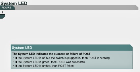
Once the power cable is connected, the switch initiates a series of tests called the power-on self test (POST). POST runs automatically to verify that the switch functions correctly. The System LED indicates the success or failure of POST. If the System LED is off but the switch is plugged in, then POST is running. If the System LED is green, then POST was successful. If the System LED is amber, then POST failed. POST failure is considered to be a fatal error. Reliable operation of the switch should not be expected if POST fails.
The Port Status LEDs also change during POST. The Port Status LEDs turn amber for about 30 seconds as the switch discovers the network topology and searches for loops. If the Port Status LEDs turn green, the switch has established a link between the port and a target, such as a computer. If the Port Status LEDs turn off, the switch has determined that nothing is plugged into the port.
The next page will teach students how to establish a communication session with a switch.


No comments:
Post a Comment