
Network Testing / Introduction to network testing

Network Testing
>Introduction to network testing
9.2.1 This page will give students an overview of how to test a network.
Basic testing of a network should proceed in sequence from one OSI reference model layer to the next. Begin with Layer 1 and work up to Layer 7, if necessary. At Layer 1, look for simple problems such as power cords plugged in the wall and other physical connections. The most common problems that occur on IP networks result from errors in the addressing scheme. It is important to test the address configuration before continuing with further configuration steps.
Each test presented in this lesson focuses on network operations at a specific layer of the OSI model. At Layer 3, the commands telnet and ping are used to test the network.
The next page will discuss the troubleshooting process.

Comments

Popular posts from this blog

OSI layers / Peer-to-peer communications / TCP/IP model

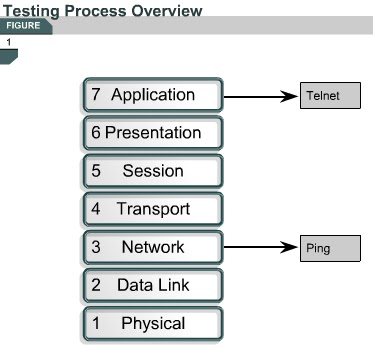
OSI layers 2.3.4 This page discusses the seven layers of the OSI model. The OSI reference model is a framework that is used to understand how information travels throughout a network. The OSI reference model explains how packets travel through the various layers to another device on a network, even if the sender and destination have different types of network media. In the OSI reference model, there are seven numbered layers, each of which illustrates a particular network function. - Dividing the network into seven layers provides the following advantages: • It breaks network communication into smaller, more manageable parts. • It standardizes network components to allow multiple vendor development and support. • It allows different types of network hardware and software to communicate with each other. • It prevents changes in one layer from affecting other layers. • It divides network communication into smaller parts to make learning it easier to understand. In the foll...

PC Basic...

• Backplane – A backplane is an electronic circuit board containing circuitry and sockets into which additional electronic devices on other circuit boards or cards can be plugged; in a computer, generally synonymous with or part of the motherboard. • Network interface card (NIC) – An expansion board inserted into a computer so that the computer can be connected to a network. • Video card – A board that plugs into a PC to give it display capabilities. • Audio card – An expansion board that enables a computer to manipulate and output sounds. • Parallel port – An interface capable of transferring more than one bit simultaneously that is used to connect external devices such as printers. • Serial port – An interface that can be used for serial communication in which only one bit is transmitted at a time. • Mouse port – A port used to connect a mouse to a PC. • USB port – A Universal Serial Bus connector. A USB port connects devices such as a mouse or printer to the computer ...

1.2.2 RIP V2 Features

 1.2.2 RIP V2 Features This page will discuss RIP v2, which is an improved version of RIP v1. Both versions of RIP share the following features: It is a distance vector protocol that uses a hop count metric. It uses hold down timers to prevent routing loops – default is 180 seconds. It uses split horizon to prevent routing loops. It uses 16 hops as a metric for infinite distance. RIP v2 provides prefix routing, which allows it to send out subnet mask information with the route update. Therefore, RIP v2 supports the use of classless routing in which different subnets within the same network can use different subnet masks, as in VLSM. RIP v2 provides for authentication in its updates. A set of keys can be used on an interface as an authentication check. RIP v2 allows for a choice of the type of authentication to be used in RIP v2 packets. The choice can be either clear text or Message-Digest 5 (MD5) encryption. Clear text is the default. MD5 can be used t...