Friday, October 18, 2013

Examining help in the switch CLI

Examining help in the switch CLI 

Context Sensitive Help
Console Error Messages
Command History Buffer
Provides a list of commands and the arguments associated with a specific command.
Identifies problems with any switch commands that are incorrectly entered so that the operator can alter or correct them.
Allows recall of long or complex commands or entries for reentry, review, or correction.

6.1.5 This page will explain how the help system is used in the CLI of Cisco switches.
The CLI for Cisco switches is very similar to the CLI for Cisco routers.
To use the help system enter a question mark (?). When this sign is entered at the system prompt, a list of commands available for the current command mode is displayed. 
The help system is very flexible. To obtain a list of commands that begin with a particular character sequence, enter those characters followed immediately by the question mark (?). Do not enter a space before the question mark. This form of help is called word help, because it completes a word.
To list keywords or arguments that are associated with a particular command, enter one or more words associated with the command, followed by a space and then a question mark (?). This form of help is called command syntax help, because it provides applicable keywords or arguments based on a partial command.
The Interactive Media Activity will help students understand how switches reduce the size of collision domains.

The next page will discuss switch command modes.

Viewing initial bootup output from the switch

Viewing initial bootup output from the switch 
6.1.4 This page will explain how HyperTerminal can be used to check and configure a switch.
In order to configure or check the status of a switch, connect a computer to the switch in order to establish a communication session. Use a rollover cable to connect the console port on the back of the switch to a COM port on the back of the computer. 
Start HyperTerminal on the computer. A dialog window will be displayed. The connection must first be named when initially configuring the HyperTerminal communication with the switch. Select the COM port to which the switch is connected from the pull-down menu, and click the OK button. A second dialog window will be displayed. Set up the parameters and click the OK button.
Plug the switch into a wall outlet. The initial bootup output from the switch should be displayed on the HyperTerminal screen. This output shows information about the switch, details about POST status, and data about the switch hardware.
After the switch has booted and completed POST, prompts for the System Configuration dialog are presented. The switch may be configured manually with or without the assistance of the System Configuration dialog. The System Configuration dialog on the switch is simpler than that on a router.
The next page will explain how the help command is used in Cisco switches.

Verifying port LEDs during switch POST

Verifying port LEDs during switch POST 
6.1.3 There are many ideas to present here. The following could help in answering some of the questions students might ask about POST LEDs during switch POST:
  • At the start all port LEDs are green
  • Each LED turns off after its test completes
  • If a test fails, its LED turns amber
  • System LED turns amber if any test fails
  • If no test fails, POST completes
  • On POST completion, LEDs blink 
Port LED Display Mode
Description
Port status (STAT LED on)
Off: No link present
Green: Link present, no activity
Flashing green: Link present with traffic activity
Alternating green and amber: Link fault. Error frames can affect connectivity. Excessive collisions and cyclic redundancy check (CRC), alignment, and jabber errors are monitored for a link-fault indication.
Amber: Port not forwarding because management disabled the port, suspended because of an address violation, or suspended by Spanning-Tree Protocol (STP) because of network loops.
Bandwidth utilization (UTL LED on)
Green: Current bandwidth utilization displayed over the amber LED background on a logarithmic scale
Amber: Maximum backplane utilization since the switch was powered on Green and amber: Depends on model as follows:
If all LEDs on Catalyst 2950-12, 2950-24, 2950C-24, and 2950T-24 switches are green, the switch is using 50 percent or more of the total bandwidth. If the far-right LED is off, the switch is using more than 25 but less than 50 percent of the total bandwidth, and so on. If only the far-left LED is green, the switch is using less than 0.0488 percent of the total bandwidth.
If all LEDs on Catalyst 2950G-12-EI switches are green, the switch is using 50 percent or more of the total bandwidth. If the LED for GBIC module slot 2 is off, the switch is using more than 25 but less than 50 percent of the total bandwidth. If LEDs for both GBIC module slots are off, the switch is using less than 25 percent of the total bandwidth, and so on.
If all LEDs on Catalyst 2950G-24-EI and 2950G-24-EI-DC switches are green, the switch is using 50 percent or more of the total bandwidth.
If the LED for GBIC module slot 2 is off, the switch is using more than 25 but less than 50 percent of the total bandwidth. If LEDs for both GBIC module slots are off, the switch is using less than 25 percent of the total bandwidth, and so on.
If all LEDs on Catalyst 2950G-48-EI switches are green, the switch is using 50 percent or more of the total bandwidth. If the LED for the upper GBIC module slot is off, the switch is using more than 25 but less than 50 percent of the total bandwidth. If LEDs for both GBIC module slots are off, the switch is using less than 25 percent of the total bandwidth, and so on.
Full duplex (FDUP LED on)
Green: Ports configured in full-duplex mode
Off: Ports using half-duplex mode

This page will explain how LEDs can be used to determine if a switch works properly and has established a link with its target.
Once the power cable is connected, the switch initiates a series of tests called the power-on self test (POST). POST runs automatically to verify that the switch functions correctly. The System LED indicates the success or failure of POST. If the System LED is off but the switch is plugged in, then POST is running. If the System LED is green, then POST was successful. If the System LED is amber, then POST failed. POST failure is considered to be a fatal error. Reliable operation of the switch should not be expected if POST fails.
The Port Status LEDs also change during POST. The Port Status LEDs turn amber for about 30 seconds as the switch discovers the network topology and searches for loops. If the Port Status LEDs turn green, the switch has established a link between the port and a target, such as a computer. If the Port Status LEDs turn off, the switch has determined that nothing is plugged into the port.
The next page will teach students how to establish a communication session with a switch.


Switch LED indicators

Switch LED indicators 
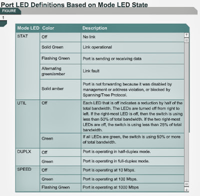
6.1.2 The front panel of a switch has several lights to help monitor system activity and performance. These lights are called light-emitting diodes (LEDs). This page will discuss the LEDs on the front of a switch:
  • System LED
  • Remote Power Supply (RPS) LED
  • Port Mode LEDs
  • Port Status LEDs
The System LED shows whether the system is receiving power and functioning correctly.
The RPS LED indicates whether or not the remote power supply is in use.
The Mode LEDs indicate the state of the Mode button. The modes are used to determine how the Port Status LEDs are interpreted. To select or change the port mode, press the Mode button repeatedly until the Mode LEDs indicate the desired mode.
Figure describes the Port Status LED colors as these are dependent on the value of the Mode LEDs.
The next page will explain how LEDs are used to verify the functionality of a switch.

Physical startup of the Catalyst switch

Physical startup of the Catalyst switch 
6.1.1
The following are points to observe before starting the switch:
  • Verify the cable and console connection.
  • Attach the power cable plug to the switch power supply socket.
  • Observe the boot sequence:
  • LEDs on the switch chassis
  • Cisco IOS software output text
The following are points to observe during the initial startup of a Catalyst switch:

  • System startup routines initiate the switch software
  • Initial startup uses default configuration parameters
Step
Action
1
Before starting the switch, verify the following:
  • All network cable connections are secure.
  • The terminal is connected to the console point.
  • A console terminal application, such as HyperTerminal, is selected.
2
Attach the power cable plug to the switch power supply socket. The switch should power up. Note that most switches do not have on/off switches.
3
Observe the following boot sequence:
  • LEDs on the switch chassis
  • Cisco IOS software output text
This page will explain the features, functions, and startup of switches.
Switches are dedicated, specialized computers that contain a central processing unit (CPU), random access memory (RAM), and an operating system. As shown in Figure , switches usually have several ports that hosts can connect to, as well as specialized ports for the purpose of management. Switches can be managed and the configuration can be viewed and changed through the console port.
Switches typically have no power switch to turn them on and off. They simply connect or disconnect from a power source.
Several switches from the Cisco Catalyst 2900 series are shown in Figure . There are 12-port, 24-port, and 48-port models. The top two switches in Figure are fixed configuration symmetrical switches that offer FastEthernet on all ports or a combination of 10Mbps and 100Mbps ports. The next three switches are asymmetrical models with two fixed fiber or copper Gigabit Ethernet ports. The bottom four switches are asymmetrical models with modular Gigabit Interface Converter (GBIC) slots, which can accommodate a variety of copper and fiber media options.
The next page will discuss LED indicators on a switch.

Module 6: Switch Configuration / Overview

Switch Configuration / Overview

When teaching Module 6, explain how a Catalyst switch goes through its startup on powering up. When the startup is complete, the initial software settings may be configured. In this module students will have the opportunity to complete a series of hands-on labs that should help them feel comfortable with the command-line interface (CLI) configuration of switches. Comparisons can be made between the ways students have been programming routers and the way they will program switches. It is suggested that the case study be examined along with the work in this module, since the students will begin programming the switches. Relate what they are learning to the case study.

CAUTION:
This module contains many hands-on labs and instructors are encouraged to assist their students in completing as many of these labs as possible. Prepare the students to see different outputs based on the type of switch they are using. Some academies may be using the menu driven switches, so instructors need to ensure that these students understand how to program the CLI switches. This could be achieved by the use of mini-lectures and demonstrations.

A switch is a Layer 2 network device that acts as the concentration point for the connection of workstations, servers, routers, hubs, and other switches.
A hub is an older type of concentration device that also provides multiple ports. However, hubs are inferior to switches because all devices connected to a hub share the bandwidth and the same collision domain. Another drawback to hubs is that they only operate in half-duplex mode. In half-duplex mode, hubs can only send or receive data at any given time, but they cannot do both at the same time. Switches can operate in full-duplex mode, which means they can send and receive data simultaneously.
Switches are multi-port bridges. Switches are the current standard technology for Ethernet LANs that utilize a star topology. A switch provides many dedicated, point-to-point virtual circuits between connected network devices, so collisions are not likely to occur.
Because of the dominant role of switches in modern networks, the ability to understand and configure switches is essential for network support.
New switches have a preset configuration with factory defaults. This configuration rarely meets the needs of network administrators. Switches can be configured and managed from a command-line interface (CLI). Network devices can also be configured and managed through a web based interface and a browser.
Network administrators must be familiar with all tasks associated with the management of networks with switches. Some of these tasks include maintenance of the switch and its IOS. Other tasks include management of the interfaces and tables for optimal, reliable, and secure operation. Basic switch configuration, IOS upgrades, and password recovery are essential network administrator skills.
This module covers some of the objectives for the CCNA 640-801 and ICND 640-811 exams. 
Students who complete this module should be able to perform the following tasks: 
  • Identify the major components of a Catalyst switch
  • Monitor switch activity and status with the use of LED indicators
  • Examine the switch bootup output with the use of HyperTerminal
  • Use the help features of the command-line interface
  • List the major switch command modes
  • Verify the default settings of a Catalyst switch
  • Set an IP address and default gateway for the switch to allow connection and management over a network
  • View the switch settings with a Web browser
  • Configure interfaces for speed and duplex operation
  • Examine and manage the switch MAC address table
  • Configure port security
  • Manage configuration files and IOS images
  • Perform password recovery on a switch
  • Upgrade the IOS of a switch 


Module 5 Summary

Summary
Before moving on to Module 6, the students must be proficient in explaining the concepts of LAN switches and LAN design.
Online assessment options include the end-of-module online quiz in the curriculum and the online Module 5 exam. From memory students should be able to complete the Matching LAN Design and Goals activity and the Point and Click Core Layer activity.
An understanding of the following key points should have been achieved:
  • The four major goals of LAN design
  • Key considerations in LAN design
  • The steps in systematic LAN design
  • Design issues associated with Layers 1, 2, and 3
  • The three-layer design model
  • The functions of each of layer of the three-layer model
  • Cisco access layer switches and their features
  • Cisco distribution layer switches and their features
  • Cisco core layer switches and their features
 This page summarizes the topics discussed in this module.
LAN design depends on the requirements of individual organizations but typically focuses on functionality, scalability, manageability, and adaptability. For a LAN to be effective, it should be designed and implemented based on a planned series of systematic steps. The steps require data and requirements to be gathered and analyzed, Layers 1,2, and 3 implemented, and everything to be documented. The following are important LAN design documentation:
  • OSI layer topology map
  • LAN logical map
  • LAN physical map
  • Cut sheets
  • VLAN logical map
  • Layer 3 logical map
  • Address maps
Layer 1 design issues include the type of cables to be used and the overall structure of the cabling. This also includes the TIA/EIA-568-A standard for layout and connection of wiring schemes. Layer 1 media types include 10/100BASE-TX, Category 5, 5e, or 6 unshielded twisted-pair (UTP), or shielded twisted-pair (STP), and 100BaseFX fiber-optic cable.
The logical diagram of the LAN includes the locations and identification of the MDF and IDF wiring closets, the type and quantity of cables used to interconnect the IDFs with the MDF, and the number of spare cables available to increase the bandwidth between the wiring closets.
Layer 2 devices provide flow control, error detection, error correction, and reduce congestion in the network. Bridges and LAN switches are the two most common Layer 2 network devices. Microsegmentation of the network reduces the size of collision domains and reduces collisions. 
Routers are Layer 3 devices that can be used to create unique LAN segments. They allow communication between segments based on Layer 3 addresses, such as IP addresses. Implementation of Layer 3 devices allows for segmentation of the LAN into unique physical and logical networks. Routers also allow for connectivity to WANs such as the Internet.
VLAN implementation combines Layer 2 switching and Layer 3 routing technologies to limit both collision domains and broadcast domains. VLANs can also be used to provide security by creating the VLAN groups according to function and by using routers to communicate between VLANs.
The hierarchical design model includes three layers. The access layer provides users in workgroups, access to the network. The distribution layer provides policy-based connectivity. The core layer provides optimal transport between sites. The core layer is often referred to as the backbone.
Access layer switches operate at Layer 2 of the OSI model and provide services such as VLAN membership. The main purpose of an access layer switch is to allow end users into the network. An access layer switch should provide this functionality with low cost and high port density.
The distribution layer switch is a point at which a broadcast domain is delineated. The distribution layer combines VLAN traffic and is a focal point for policy decisions about traffic flow. For these reasons, distribution layer switches operate at both Layer 2 and Layer 3 of the OSI model. Switches in this layer are referred to as multilayer switches.
The core layer is a high-speed switching backbone. This layer of the network design should not perform any packet manipulation. Packet manipulation, such as access list filtering, would slow down the switching of packets. A core infrastructure with redundant alternate paths give stability to the network in the event of a single device failure.