Thursday, October 17, 2013

Microsegmentation implementation

Microsegmentation implementation 
4.3.6 This page will explain the functions of a switch in a LAN due to microsegmentation.
LAN switches are considered multi-port bridges with no collision domain, because of microsegmentation. Data is exchanged at high speeds by switching the frame to its destination. By reading the destination MAC address Layer 2 information, switches can achieve high-speed data transfers, much like a bridge does. This process leads to low latency levels and a high rate of speed for frame forwarding.  
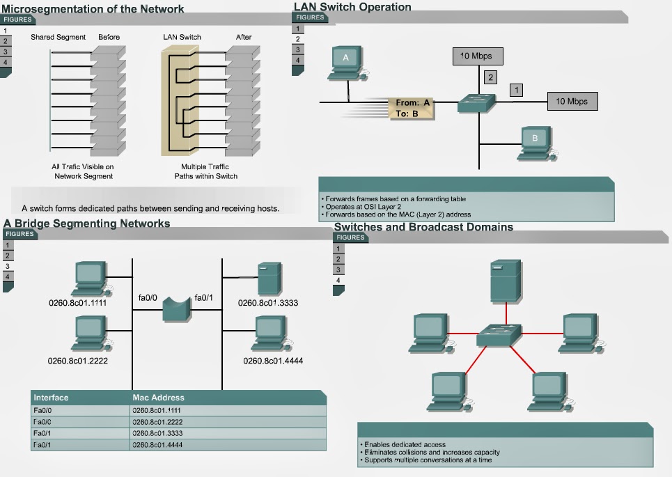
Ethernet switching increases the bandwidth available on a network. It does this by creating dedicated network segments, or point-to-point connections, and connecting these segments in a virtual network within the switch. This virtual network circuit exists only when two nodes need to communicate. This is called a virtual circuit because it exists only when needed, and is established within the switch.
Even though the LAN switch reduces the size of collision domains, all hosts connected to the switch are still in the same broadcast domain. Therefore, a broadcast from one node will still be seen by all the other nodes connected through the LAN switch.
Switches are data link layer devices that, like bridges, enable multiple physical LAN segments to be interconnected into a single larger network. Similar to bridges, switches forward and flood traffic based on MAC addresses. Because switching is performed in hardware instead of in software, it is significantly faster. Each switch port can be considered a micro-bridge acting as a separate bridge and gives the full bandwidth of the medium to each host.
The next page will discuss collisions.

Reading people of this web site can help me? reply must

Reading people of this web site can help me? reply must

Those people are studying my website which helping  for you for futuring regarding NETWORKING. Can you help me by donating just $30 (US Dollar) per person to me or any amount as you can donate. I will thankful for your sympetheic help for me.

You can send through Western Union and send to me the code and you can send this code to me via email address and you can see my email addresses on my website "Main page".

Note:- A good news for you people. I have prepared Power point presentation related to CCNA Full track and you people just email to me and send your full detail for my record purpose. Then i will send you all presentation to you via email.
And CCNP is near to complete, i hope you people will enjoy.

Why segment LANs?

Why segment LANs? 
4.3.5 Highlight that there are two primary reasons for segmenting a LAN. The first is to isolate traffic between segments. The second reason is to achieve more bandwidth per user by creating smaller collision domains. By this stage, students have heard of this term several times but instructors are encouraged to make sure that students understand the difference between collision and broadcast domains. The three figures are particularly useful.

This page will explain the two main reasons to segment a LAN.
There are two primary reasons for segmenting a LAN. The first is to isolate traffic between segments. The second reason is to achieve more bandwidth per user by creating smaller collision domains.
Without LAN segmentation, LANs larger than a small workgroup could quickly become clogged with traffic and collisions.
LAN segmentation can be implemented through the utilization of bridges, switches, and routers. Each of these devices has particular pros and cons.
With the addition of devices like bridges, switches, and routers the LAN is segmented into a number of smaller collision domains. In the example shown, four collision domains have been created.
By dividing large networks into self-contained units, bridges and switches provide several advantages. Bridges and switches will diminish the traffic experienced by devices on all connected segments, because only a certain percentage of traffic is forwarded. Bridges and switches reduce the collision domain but not the broadcast domain.
Each interface on the router connects to a separate network. Therefore the insertion of the router into a LAN will create smaller collision domains and smaller broadcast domains. This occurs because routers do not forward broadcasts unless programmed to do so.
A switch employs "microsegmentation" to reduce the collision domain on a LAN. The switch does this by creating dedicated network segments, or point-to-point connections. The switch connects these segments in a virtual network within the switch.
This virtual network circuit exists only when two nodes need to communicate. This is called a virtual circuit as it exists only when needed, and is established within the switch.
The next page will discuss microsegmentation.

How switches and bridges filter frames

How switches and bridges filter frames 
4.3.4 If the frame is addressed for another LAN, the bridge copies the frame onto the second LAN. Ignoring a frame is called filtering. Copying the frame is called forwarding.
Emphasize that a bridge is considered a store-and-forward device because it must examine the destination address field and calculate the cyclic redundancy check (CRC) in the frame check sequence field before forwarding the frame to all ports. Students may need a further explanation of the term CRC. Encourage them to check the glossary for an explanation of this term. If the destination port is busy, the bridge can temporarily store the frame until the port is available. The time it takes to perform these tasks slows the network transmissions and causes increased latency.

This page will explain how switches and bridges filter frames. In this discussion, the terms “switch” and “bridge” are synonymous.
Most switches are capable of filtering frames based on any Layer 2 frame field. For example, a switch can be programmed to reject, not forward, all frames sourced from a particular network. Because link layer information often includes a reference to an upper-layer protocol, switches can usually filter on this parameter. Furthermore, filters can be helpful in dealing with unnecessary broadcast and multicast packets.
Once the switch has built the local address table, it is ready to operate. When it receives a frame, it examines the destination address. If the frame address is local, the switch ignores it. If the frame is addressed for another LAN segment, the switch copies the frame onto the second segment.
  • Ignoring a frame is called filtering.
  • Copying the frame is called forwarding.
Basic filtering keeps local frames local and sends remote frames to another LAN segment.
Filtering on specific source and destination addresses performs the following actions:
  • Stopping one station from sending frames outside of its local LAN segment
  • Stopping all "outside" frames destined for a particular station, thereby restricting the other stations with which it can communicate
Both types of filtering provide some control over internetwork traffic and can offer improved security.
Most Ethernet switches can now filter broadcast and multicast frames. Bridges and switches that can filter frames based on MAC addresses can also be used to filter Ethernet frames by multicast and broadcast addresses. This filtering is achieved through the implementation of virtual local-area networks or VLANs. VLANs allow network administrators to prevent the transmission of unnecessary multicast and broadcast messages throughout a network. Occasionally, a device will malfunction and continually send out broadcast frames, which are copied around the network. This is called a broadcast storm and it can significantly reduce network performance. A switch that can filter broadcast frames makes a broadcast storm less harmful.
Today, switches are also able to filter according to the network-layer protocol. This blurs the demarcation between switches and routers. A router operates on the network layer using a routing protocol to direct traffic around the network. A switch that implements advanced filtering techniques is usually called a brouter. Brouters filter by looking at network layer information but they do not use a routing protocol.
The next page will explain how switches are used to segment a LAN. 

How switches and bridges learn addresses

How switches and bridges learn addresses 
4.3.3 This page will explain how bridges and switches learn addresses and forward frames.
Bridges and switches only forward frames that need to travel from one LAN segment to another. To accomplish this task, they must learn which devices are connected to which LAN segment. 
A bridge is considered an intelligent device because it can make decisions based on MAC addresses. To do this, a bridge refers to an address table. When a bridge is turned on, broadcast messages are transmitted asking all the stations on the local segment of the network to respond. As the stations return the broadcast message, the bridge builds a table of local addresses. This process is called learning.
Bridges and switches learn in the following ways:
  • Reading the source MAC address of each received frame or datagram
  • Recording the port on which the MAC address was received
In this way, the bridge or switch learns which addresses belong to the devices connected to each port.
The learned addresses and associated port or interface are stored in the addressing table. The bridge examines the destination address of all received frames. The bridge then scans the address table searching for the destination address.
The switching table is stored using Content Addressable Memory (CAM). CAM is used in switch applications to perform the following functions:
  • To take out and process the address information from incoming data packets
  • To compare the destination address with a table of addresses stored within it
The CAM stores host MAC addresses and associated port numbers. The CAM compares the received destination MAC address against the CAM table contents. If the comparison yields a match, the port is provided, and the switch forwards the packet to the correct port and address. 
An Ethernet switch can learn the address of each device on the network by reading the source address of each frame transmitted and noting the port where the frame entered the switch. The switch then adds this information to its forwarding database. Addresses are learned dynamically. This means that as new addresses are read, they are learned and stored in CAM. When a source address is not found in CAM, it is learned and stored for future use.
Each time an address is stored, it is time stamped. This allows for addresses to be stored for a set period of time. Each time an address is referenced or found in CAM, it receives a new time stamp. Addresses that are not referenced during a set period of time are removed from the list. By removing aged or old addresses, CAM maintains an accurate and functional forwarding database.
The processes followed by the CAM are as follows:
  1. If the address is not found, the bridge forwards the frame out all ports except the port on which it was received. This process is called flooding. The address may also have been deleted by the bridge because the bridge software was recently restarted, ran short of address entries in the address table, or deleted the address because it was too old. Since the bridge does not know which port to use to forward the frame, it will send it to out all ports, except the one from which it was received. It is clearly unnecessary to send it back to the same cable segment from which it was received, since any other computer or bridges on this cable must already have received the packet.
  2. If the address is found in an address table and the address is associated with the port on which it was received, the frame is discarded. It must already have been received by the destination.
  3. If the address is found in an address table and the address is not associated with the port on which it was received, the bridge forwards the frame to the port associated with the address.
If the address is found in an address table and the address is not associated with the port on which it was received, the bridge forwards the frame to the port associated with the address.
The next page will describe the process that is used to filter frames. 

Frame transmission modes

Frame transmission modes 
4.3.2 This page will describe the three main frame transmission modes: 
  • Cut-through - A switch that performs cut-through switching only reads the destination address when receiving the frame. The switch begins to forward the frame before the entire frame arrives. This mode decreases the latency of the transmission, but has poor error detection. There are two forms of cut-through switching:
    1. Fast-forward switching - This type of switching offers the lowest level of latency by immediately forwarding a packet after receiving the destination address. Latency is measured from the first bit received to the first bit transmitted, or first in first out (FIFO). This mode has poor LAN switching error detection.
    2. Fragment-free switching - This type of switching filters out collision fragments, with are the majority of packet errors, before forwarding begins. Usually, collision fragments are smaller than 64 bytes. Fragment-free switching waits until the received packet has been determined not to be a collision fragment before forwarding the packet. Latency is also measured as FIFO.
  • Store-and-forward - The entire frame is received before any forwarding takes place. The destination and source addresses are read and filters are applied before the frame is forwarded. Latency occurs while the frame is being received. Latency is greater with larger frames because the entire frame must be received before the switching process begins. The switch has time available to check for errors, which allows more error detection.
  • Adaptive cut-through - This transmission mode is a hybrid mode that is a combination of cut-through and store-and-forward. In this mode, the switch uses cut-through until it detects a given number of errors. Once the error threshold is reached, the switch changes to store-and-forward mode.
The next page will explain how switches learn about the network. 

Switch Operation / Functions of Ethernet switches

Switch Operation / 
Functions of Ethernet switches 
4.3.1 the following two main functions of Ethernet switches:
  • Isolate traffic among segments
  • Achieve greater amount of bandwidth per user by creating smaller collision domains
The first function is to isolate traffic among segments. Segments are the smaller units into which the networks are divided by use of Ethernet switches. Each segment uses carrier sense multiple access/collision detect (CSMA/CD) access method to maintain data traffic flow among the users on that segment. It would be useful to refer back to the section on CSMA/CD here and show the flowchart. Such segmentation allows multiple users to send information at the same time on the different segments without slowing down the network.
The second function of an Ethernet switch is to ensure each user has more bandwidth by creating smaller collision domains. Ethernet and Fast Ethernet switches segment LANs by creating smaller collision domains. Each segment becomes a dedicated network link, like a highway lane functioning at up to 100 Mbps. Popular servers can then be placed on individual 100-Mbps links. In modern networks, a Fast Ethernet switch will often act as the backbone of a LAN, with Ethernet hubs, Ethernet switches, or Fast Ethernet hubs providing the desktop connections in workgroups.

This page will review the functions of an Ethernet switch.
A switch is a device that connects LAN segments using a table of MAC addresses to determine the segment on which a frame needs to be transmitted. Both switches and bridges operate at Layer 2 of the OSI model. 
Switches are sometimes called multiport bridges or switching hubs. Switches make decisions based on MAC addresses and therefore, are Layer 2 devices. In contrast, hubs regenerate the Layer 1 signals out of all ports without making any decisions. Since a switch has the capacity to make path selection decisions, the LAN becomes much more efficient. Usually, in an Ethernet network the workstations are connected directly to the switch. Switches learn which hosts are connected to a port by reading the source MAC address in frames. The switch opens a virtual circuit between the source and destination nodes only. This confines communication to those two ports without affecting traffic on other ports. In contrast, a hub forwards data out all of its ports so that all hosts see the data and must process it, even if that data is not intended for it. High-performance LANs are usually fully switched: 
  • A switch concentrates connectivity, making data transmission more efficient. Frames are switched from incoming ports to outgoing ports. Each port or interface can provide the full bandwidth of the connection to the host.
  • On a typical Ethernet hub, all ports connect to a common backplane or physical connection within the hub, and all devices attached to the hub share the bandwidth of the network. If two stations establish a session that uses a significant level of bandwidth, the network performance of all other stations attached to the hub is degraded.
  • To reduce degradation, the switch treats each interface as an individual segment. When stations on different interfaces need to communicate, the switch forwards frames at wire speed from one interface to the other, to ensure that each session receives full bandwidth.
To efficiently switch frames between interfaces, the switch maintains an address table. When a frame enters the switch, it associates the MAC address of the sending station with the interface on which it was received.
The main features of Ethernet switches are:
  • Isolate traffic among segments
  • Achieve greater amount of bandwidth per user by creating smaller collision domains
The first feature, isolate traffic among segments, provides for greater security for hosts on the network. Each segment uses the CSMA/CD access method to maintain data traffic flow among the users on that segment. Such segmentation allows multiple users to send information at the same time on the different segments without slowing down the network. 
By using the segments in the network fewer users and/or devices are sharing the same bandwidth when communicating with one another. Each segment has its own collision domain. Ethernet switches filter the traffic by redirecting the datagrams to the correct port or ports, which are based on Layer 2 MAC addresses.
The second feature is called microsegmentation. Microsegmentation allows the creation of dedicated network segments with one host per segment. Each hosts receives access to the full bandwidth and does not have to compete for available bandwidth with other hosts. Popular servers can then be placed on individual 100-Mbps links. Often in networks of today, a Fast Ethernet switch will act as the backbone of the LAN, with Ethernet hubs, Ethernet switches, or Fast Ethernet hubs providing the desktop connections in workgroups. As demanding new applications such as desktop multimedia or video conferencing become more popular, certain individual desktop computers will have dedicated 100-Mbps links to the network. 
The next page will introduce three frame transmission modes.