Friday, October 14, 2011

Address mask requests

Address mask requests
8.2.5 This page will explain address mask request messages and how they are used.
When a network administrator uses the process of subnetting to divide a major IP address into multiple subnets, a new subnet mask is created. This new subnet mask is important to identify network, subnet, and host bits in an IP address. If a host does not know the subnet mask, it may send an address mask request to the local router. If the address of the router is known, this request may be sent directly to the router. Otherwise, the request will be broadcast. When the router receives the request, it will respond with an address mask reply. This address mask reply will identify the correct subnet mask. For example, assume that a host is located within a Class B network and has an IP address of 172.16.5.2. This host does not know the subnet mask so it broadcasts an address mask request:
Source address: 172.16.5.2
Destination address: 255.255.255.255
Protocol:  ICMP = 1
Type: Address Mask Request = AM1
Code: 0
Mask: 255.255.255.0
This broadcast is received by 172.16.5.1, the local router. The router responds with the address mask reply:
Source address: 172.16.5.1
Destination address: 172.16.5.2
Protocol:  ICMP = 1
Type: Address Mask Reply = AM2
Code: 0
Mask: 255.255.255.0
The frame format for the address mask request and reply is shown in Figure . Figure shows the descriptions for each field in the address mask request message. Note that the same frame format is used for both the address mask request and the reply. However, an ICMP type number of 17 is assigned to the request and 18 is assigned to the reply.
The next page will introduce the ICMP router discovery message.

Information requests and reply message formats

Information requests and reply message formats 
8.2.4 This page will describe the format of ICMP information request and reply messages.
The ICMP information request and reply messages were originally intended to allow a host to determine its network number. Figure shows the format for an ICMP information request and reply message.
Two type codes are available in this message. Type 15 signifies an information request message and type 16 is an information reply message. This particular ICMP message type is considered obsolete. Other protocols such as BOOTP, Reverse Address Resolution Protocol (RARP), and Dynamic Host Configuration Protocol (DHCP) are now used to allow hosts to obtain their network numbers.
The next page will describe address mask request and reply messages.

Clock synchronization and transit time estimation

Clock synchronization and transit time estimation 
8.2.3 This page explains how ICMP timestamps are used to solve clock synchronization issues.
The TCP/IP protocol suite allows systems to connect to one another over vast distances through multiple networks. Each network provides clock synchronization in its own way. As a result, hosts on different networks who attempt to communicate with software that requires time synchronization can encounter problems. The ICMP timestamp message type is designed to help alleviate this problem.
The ICMP timestamp request message allows a host to ask for the current time according to the remote host. The remote host uses an ICMP timestamp reply message to respond to the request.
The type field on an ICMP timestamp message can be either 13 for a timestamp request or 14 for a timestamp reply. The code field value is always set to 0 because there are no additional parameters available. The ICMP timestamp request contains an originate timestamp, which is the time on the requesting host just before the timestamp request is sent. The receive timestamp is the time that the destination host receives the ICMP timestamp request. The transmit timestamp is filled in just before the ICMP timestamp reply is returned. Originate, receive, and transmit timestamps are computed in milliseconds elapsed since midnight Universal Time (UT).
All ICMP timestamp reply messages contain the originate, receive, and transmit timestamps. Using these three timestamps, the host can determine transit time across the network by subtracting the originate time from the receive time. Or it could determine transit time in the return direction by subtracting the transmit time from the current time. The host that originated the timestamp request can also estimate the local time on the remote computer.
While ICMP timestamp messages provide a simple way to estimate time on a remote host and total network transmit time, this is not the best way to obtain this information. Instead, more robust protocols such as Network Time Protocol (NTP) at the upper layers of the TCP/IP protocol stack perform clock synchronization in a more reliable manner.
The next page will discuss ICMP information request and reply messages.

ICMP redirect/change reque

ICMP redirect/change request
8.2.2 This page will introduce the ICMP redirect request, which is a common ICMP control message. This type of message can only be initiated by a gateway, which is a term commonly used to describe a router. All hosts that communicate with multiple IP networks must be configured with a default gateway. This default gateway is the address of a router port connected to the same network as the host. Figure displays a host connected to a router that has access to the Internet. After Host B is configured with the IP address of FastEthernet 0/0 as its default gateway, it uses that IP address to reach any network that is not directly connected. Normally, Host B is connected to a single gateway. However, a host may be connected to a segment that has two or more directly connected routers. In this case, the default gateway of the host may need to use a redirect/change request to inform the host of the best path to a certain network. 
Figure shows a network where ICMP redirects would be used. Host B sends a packet to Host C on network 10.0.0.0/8. Since Host B is not directly connected to the same network, it forwards the packet to its default gateway, Router A. Router A finds the correct route to network 10.0.0.0/8 by looking into its route table. It determines that the path to the network is back out the same interface the request to forward the packet came from. It forwards the packet and sends an ICMP redirect/change request to Host B. The request instructs Host B to use Router B as the gateway to forward all future requests to network 10.0.0.0/8.
Default gateways only send ICMP redirect/change request messages if the following conditions are met: 
  • The interface on which the packet comes into the router is the same interface on which the packet gets routed out.
  • The subnet/network of the source IP address is the same subnet/network of the next-hop IP address of the routed packet.
  • The datagram is not source-routed.
  • The route for the redirect is not another ICMP redirect or a default route.
  • The router is configured to send redirects. By default, Cisco routers send ICMP redirects. The interface subcommand no ip redirects will disable ICMP redirects.
The ICMP redirect/change request uses the format shown in Figure . It has an ICMP type code of 5. In addition, it has a code value of 0, 1, 2, or 3.
The Router Internet Address field in the ICMP redirect is the IP address that should be used as the default gateway for a particular network. In the example in Figure , the ICMP redirect sent from Router A to Host B would have a Router Internet Address field value of 172.16.1.200, which is the IP address of E0 on Router B.
The next page will describe clock synchronization.

TCP/IP Suite Control Messages / Introduction to control messages

Introduction to control messages 
8.2.1 This page will provide an overview of TCP/IP control messages.
ICMP is an important part of the TCP/IP protocol suite. All IP implementations must include ICMP support. The reasons for this are simple. Since IP does not guarantee delivery, it cannot inform hosts when errors occur. Second, IP has no built-in method to provide informational or control messages to hosts.
Unlike error messages, control messages are not the results of lost packets or error conditions that occur during packet transmission. Instead, they are used to inform hosts of conditions such as network congestion or the existence of a better gateway to a remote network. ICMP uses the basic IP header to travel through multiple networks.
Multiple types of control messages are used by ICMP. Some of the most common are shown in Figure . Many of these are discussed in this lesson.
The next page will describe ICMP redirect requests.

Miscellaneous error reporting

Miscellaneous error reporting
8.1.9 This page will explain what a parameter problem message is and why it occurs.
Devices that process datagrams may not be able to forward a datagram due to an error in the header parameter. This error does not relate to the state of the destination host or network but still prevents the datagram from being processed and delivered, and because of that, the datagram is discarded. In this case, an ICMP type 12 parameter problem message is sent to the source of the datagram. Figure shows the parameter problem message header.
The parameter problem message includes the pointer field in the header. When the code value is 0, the pointer field indicates the octet of the datagram that produced the error.
This page concludes this lesson. The next lesson will describe TCP/IP suite control messages. The first page will provide an overview of control messages.

Destination unreachable message


Destination unreachable message 
8.1.8 This page will explain what a destination unreachable message is and why it occurs.
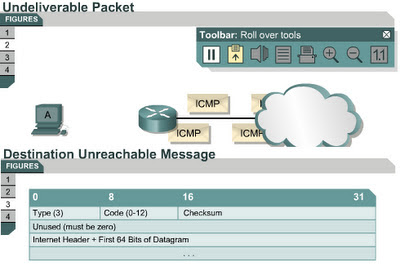
Datagrams cannot always be forwarded to their destinations. Hardware failures, improper protocol configuration, down interfaces, and incorrect routing information are some of the factors that prevent successful delivery. In these cases, ICMP sends the sender a destination unreachable message, which indicates that the datagram could not be forwarded. 
Figure shows an ICMP destination unreachable message header. The value of 3 in the type field indicates it is a destination unreachable message. The code value indicates the reason the packet could not be delivered. Figure has a code value of 0, which indicates that the network was unreachable. Figure shows the meaning for each possible code value in a destination unreachable message.
A destination unreachable message may also be sent when packet fragmentation is required to forward a packet. Fragmentation is usually necessary when a datagram is forwarded from a Token Ring network to an Ethernet network. If the datagram does not allow fragmentation, the packet cannot be forwarded, so a destination unreachable message will be sent. Destination unreachable messages may also be generated if IP-related services such as FTP or Web services are unavailable. To effectively troubleshoot an IP network, it is necessary to understand the various causes of ICMP destination unreachable messages.
The next page introduces parameter problem messages.