Friday, October 18, 2013

Module 5 Summary

Summary
Before moving on to Module 6, the students must be proficient in explaining the concepts of LAN switches and LAN design.
Online assessment options include the end-of-module online quiz in the curriculum and the online Module 5 exam. From memory students should be able to complete the Matching LAN Design and Goals activity and the Point and Click Core Layer activity.
An understanding of the following key points should have been achieved:
  • The four major goals of LAN design
  • Key considerations in LAN design
  • The steps in systematic LAN design
  • Design issues associated with Layers 1, 2, and 3
  • The three-layer design model
  • The functions of each of layer of the three-layer model
  • Cisco access layer switches and their features
  • Cisco distribution layer switches and their features
  • Cisco core layer switches and their features
 This page summarizes the topics discussed in this module.
LAN design depends on the requirements of individual organizations but typically focuses on functionality, scalability, manageability, and adaptability. For a LAN to be effective, it should be designed and implemented based on a planned series of systematic steps. The steps require data and requirements to be gathered and analyzed, Layers 1,2, and 3 implemented, and everything to be documented. The following are important LAN design documentation:
  • OSI layer topology map
  • LAN logical map
  • LAN physical map
  • Cut sheets
  • VLAN logical map
  • Layer 3 logical map
  • Address maps
Layer 1 design issues include the type of cables to be used and the overall structure of the cabling. This also includes the TIA/EIA-568-A standard for layout and connection of wiring schemes. Layer 1 media types include 10/100BASE-TX, Category 5, 5e, or 6 unshielded twisted-pair (UTP), or shielded twisted-pair (STP), and 100BaseFX fiber-optic cable.
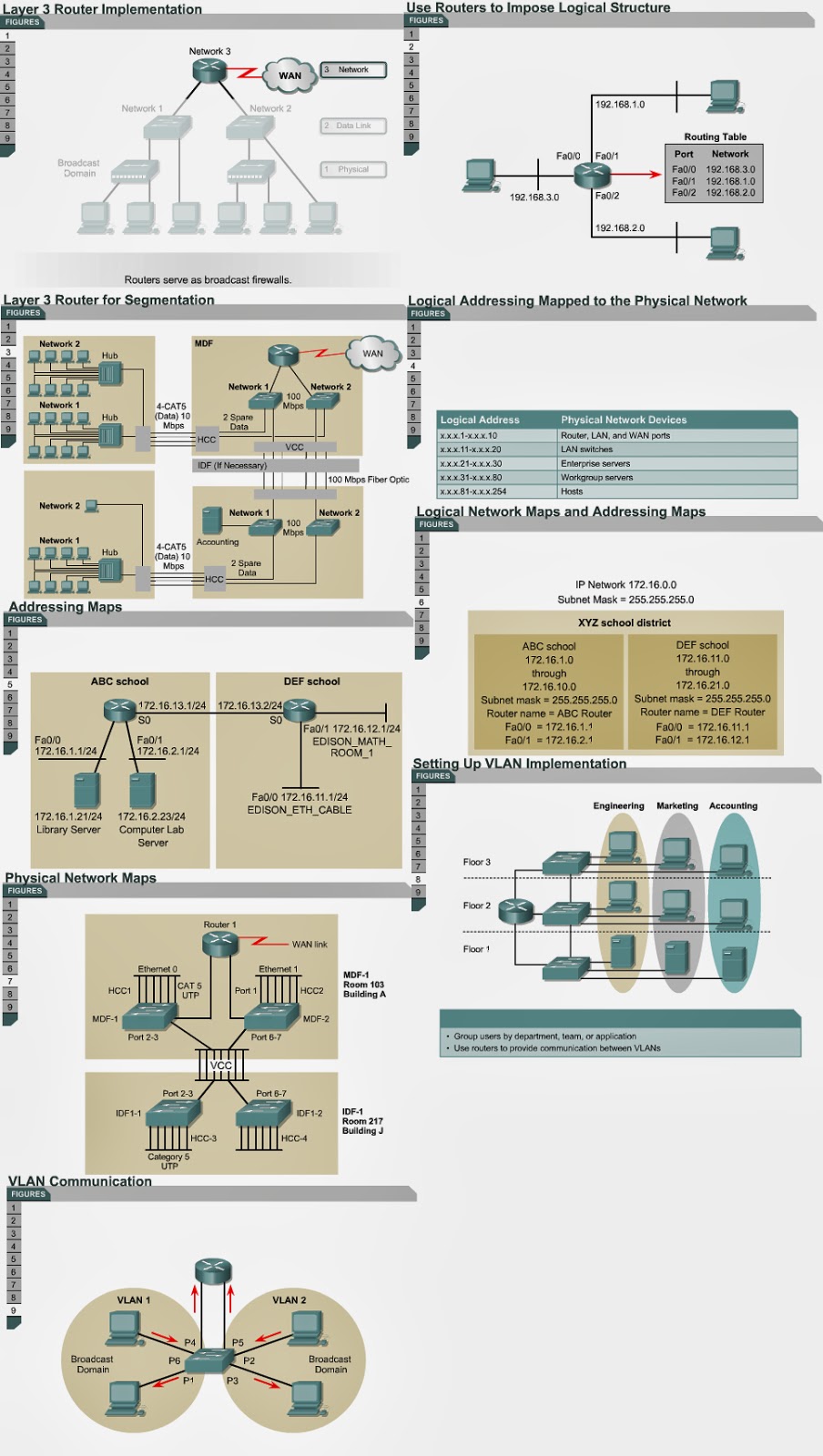
The logical diagram of the LAN includes the locations and identification of the MDF and IDF wiring closets, the type and quantity of cables used to interconnect the IDFs with the MDF, and the number of spare cables available to increase the bandwidth between the wiring closets.
Layer 2 devices provide flow control, error detection, error correction, and reduce congestion in the network. Bridges and LAN switches are the two most common Layer 2 network devices. Microsegmentation of the network reduces the size of collision domains and reduces collisions. 
Routers are Layer 3 devices that can be used to create unique LAN segments. They allow communication between segments based on Layer 3 addresses, such as IP addresses. Implementation of Layer 3 devices allows for segmentation of the LAN into unique physical and logical networks. Routers also allow for connectivity to WANs such as the Internet.
VLAN implementation combines Layer 2 switching and Layer 3 routing technologies to limit both collision domains and broadcast domains. VLANs can also be used to provide security by creating the VLAN groups according to function and by using routers to communicate between VLANs.
The hierarchical design model includes three layers. The access layer provides users in workgroups, access to the network. The distribution layer provides policy-based connectivity. The core layer provides optimal transport between sites. The core layer is often referred to as the backbone.
Access layer switches operate at Layer 2 of the OSI model and provide services such as VLAN membership. The main purpose of an access layer switch is to allow end users into the network. An access layer switch should provide this functionality with low cost and high port density.
The distribution layer switch is a point at which a broadcast domain is delineated. The distribution layer combines VLAN traffic and is a focal point for policy decisions about traffic flow. For these reasons, distribution layer switches operate at both Layer 2 and Layer 3 of the OSI model. Switches in this layer are referred to as multilayer switches.
The core layer is a high-speed switching backbone. This layer of the network design should not perform any packet manipulation. Packet manipulation, such as access list filtering, would slow down the switching of packets. A core infrastructure with redundant alternate paths give stability to the network in the event of a single device failure.

Core layer switches

Core layer switches 
5.2.6 The core layer is the backbone of the campus switched network. The switches in this layer can make use of a number of Layer 2 technologies. Provided that the distance between the core layer switches is not too great, the switches can use Ethernet technology. Other Layer 2 technologies such as ATM cell switching, can also be used. In a network design, the core layer can be a routed, or Layer 3, core. Core layer switches are designed to provide efficient Layer 3 functionality when needed. Factors such as need, cost, and performance should be considered before a choice is made.
The following Cisco switches are suitable for the core layer: 
  • Catalyst 6500 series
  • Catalyst 8500 series
  • IGX 8400 series
  • Lightstream 1010
This page concludes this lesson. The next page will summarize the main points from this module.

Distribution layer switches

Distribution layer switches 
5.2.4 This page will explain the features and functions of distribution layer switches.
Distribution layer switches are the aggregation points for multiple access layer switches. The switch must be able to accommodate the total amount of traffic from the access layer devices.
The distribution layer switch must have high performance. The distribution layer switch is a point at which a broadcast domain is delineated. The distribution layer combines VLAN traffic and is a focal point for policy decisions about traffic flow. For these reasons, distribution layer switches operate at both Layer 2 and Layer 3 of the OSI model. Switches in this layer are referred to as multilayer switches. These multilayer switches combine the functions of a router and a switch in one device. They are designed to switch traffic to gain higher performance than a standard router. If they do not have an associated router module, then an external router is used for the Layer 3 function.
The following Cisco switches are suitable for the distribution layer: 
  • Catalyst 2926G 
  • Catalyst 5000 family
  • Catalyst 6000 family  
The next page will describe the core layer.

Core layer overview 
5.2.5 The core layer is a high-speed switching backbone. If they do not have an associated router module, an external router is used for the Layer 3 function. This layer of the network design should not perform any packet manipulation. Packet manipulation, such as access list filtering, would slow down the switching of packets. A core infrastructure with redundant alternate paths gives stability to the network in the event of a single device failure.
The core can be designed to use Layer 2 or Layer 3 switching. ATM or Ethernet switches can be used.
The Interactive Media Activity will require students to identify the main functions of the access, distribution, and core layers.
The next page will discuss core layer switches.

Access layer switches / Distribution layer overview

Access layer switches 
5.2.2 Access layer switches operate at Layer 2 of the OSI model and provide services such as VLAN membership. The main purpose of an access layer switch is to allow end users into the network. An access layer switch should provide this functionality with low cost and high port density.
The following Cisco switches are commonly used at the access layer:
  • Catalyst 1900 series
  • Catalyst 2820 series
  • Catalyst 2950 series
  • Catalyst 4000 series
  • Catalyst 5000 series
The Catalyst 1900 or 2820 series switch is an effective access device for small or medium campus networks. The Catalyst 2950 series switch effectively provides access for servers and users that require higher bandwidth. This is achieved with Fast Ethernet capable switch ports. The Catalyst 4000 and 5000 series switches include Gigabit Ethernet ports and are effective access devices for a larger number of users in large campus networks.
The Interactive Media Activities will describe the features of the Cisco Catalyst 1912, 2950, and 4006 switches.
The next page will discuss the distribution layer.

Distribution layer overview 
5.2.3 The distribution layer of the network is between the access and core layers. It helps to define and separate the core. The purpose of this layer is to provide a boundary definition in which packet manipulation can take place. Networks are segmented into broadcast domains by this layer. Policies can be applied and access control lists can filter packets. The distribution layer does not allow the problems to affect the core layer. The distribution layer also prevents these problems from affecting the core layer. Switches in this layer operate at Layer 2 and Layer 3. The following are some of the distribution layer functions in a switched network:
  • Aggregation of the wiring closet connections
  • Broadcast/multicast domain definition
  • VLAN routing
  • Any media transitions that need to occur
  • Security
The next page will discuss distribution layer switches.

Thursday, October 17, 2013

LAN Switches / Switched LANs, access layer overview

LAN Switches
Switched LANs, access layer overview 
5.2.1 The construction of a LAN that satisfies the needs of both medium and large-sized organizations is more likely to be successful if a hierarchical design model is used. The use of a hierarchical design model will make it easier to make changes to the network as the organization grows. This page will discuss the three layers of the hierarchical design model:
  • The access layer provides users in workgroups access to the network.
  • The distribution layer provides policy-based connectivity.
  • The core layer provides optimal transport between sites. The core layer is often referred to as the backbone.
This hierarchical model applies to any network design. It is important to realize that these three layers may exist in clear and distinct physical entities. However, this is not a requirement. These layers are defined to aid in successful network design and to represent functionality that must exist in a network.
The access layer is the entry point for user workstations and servers to the network. In a campus LAN the device used at the access layer can be a switch or a hub.
If a hub is used, bandwidth is shared. If a switch is used, then bandwidth is dedicated. If a workstation or server is directly connected to a switch port, then the full bandwidth of the connection to the switch is available to the connected computer. If a hub is connected to a switch port, bandwidth is shared between all devices connected to the hub.
Access layer functions also include MAC layer filtering and microsegmentation. MAC layer filtering allows switches to direct frames only to the switch port that is connected to the destination device. The switch creates small Layer 2 segments called microsegments. The collision domain can be as small as two devices. Layer 2 switches are used in the access layer.
The next page will describe access layer switches.

Layer 3 design

 Layer 3 design 
5.1.6 This page will describe some Layer 3 design considerations.
A router is a Layer 3 device and is considered one of the most powerful devices in the network topology.
Layer 3 devices can be used to create unique LAN segments. Layer 3 devices allow communication between segments based on Layer 3 addresses, such as IP addresses. Implementation of Layer 3 devices allows for segmentation of the LAN into unique physical and logical networks. Routers also allow for connectivity to WANs, such as the Internet. 
Layer 3 routing determines traffic flow between unique physical network segments based on Layer 3 addresses. A router forwards data packets based on destination addresses. A router does not forward LAN-based broadcasts such as ARP requests. Therefore, the router interface is considered the entry and exit point of a broadcast domain and stops broadcasts to other LAN segments.
Routers provide scalability because they serve as firewalls for broadcasts and they can divide networks into subnetworks, or subnets, based on Layer 3 addresses. 
In order to decide whether to use routers or switches, it is important to determine the problem that needs to be solved. If the problem is related to protocol rather than issues of contention, then routers are the appropriate solution. Routers solve problems with excessive broadcasts, protocols that do not scale well, security issues, and network layer addresses. Routers are more expensive and more difficult to configure than switches.
Figure shows an example of an implementation that has multiple networks. All data traffic from Network 1 destined for Network 2 has to go through the router. In this implementation, there are two broadcast domains. The two networks have unique Layer 3 network address schemes. Multiple physical networks can be created if the horizontal cabling and vertical cabling are patched into the appropriate Layer 2 switch. This can be done with patch cables. This implementation also provides robust security because all traffic in and out of the LAN must pass through the router.
Once an IP address scheme is developed for a client, it should be clearly documented. A standard convention should be set for addresses of important hosts on the network. This address scheme should be kept consistent throughout the entire network. Address maps provide a snapshot of the network.   Physical maps of the network helps to troubleshoot the network. 
VLAN implementation combines Layer 2 switching and Layer 3 routing technologies to limit both collision domains and broadcast domains. VLANs also provide security with the creation of VLAN groups that communicate with other VLANs through routers. 
A physical port association is used to implement VLAN assignment. Ports P1, P4, and P6 have been assigned to VLAN 1. VLAN 2 has ports P2, P3, and P5. Communication between VLAN 1 and VLAN 2 can occur only through the router. This limits the size of the broadcast domains and uses the router to determine whether VLAN 1 can talk to VLAN 2. 
This page concludes this lesson. The next lesson will describe LAN switches. The first page describes the hierarchical design model.

Layer 2 design

Layer 2 design 
5.1.5 This page will discuss some important Layer 2 design considerations.
The purpose of Layer 2 devices in the network is to switch frames based on destination MAC address information, provide error detection, and to reduce congestion in the network. The two most common Layer 2 network devices are bridges and LAN switches. Devices at Layer 2 determine the size of the collision domains. 
Collisions and collision domain size are two factors that negatively affect the performance of a network. Microsegmentation of the network reduces the size of collision domains and reduces collisions.  Micro segmentation is implemented through the use of bridges and switches. The goal is to boost performance for a workgroup or a backbone. Switches can be used with hubs to provide the appropriate level of performance for different users and servers.
Another important characteristic of a LAN switch is how it allocates bandwidth on a per-port basis. This provides more bandwidth to vertical cabling, uplinks, and servers. This type of switching is referred to as asymmetric switching. Asymmetric switching provides switched connections between ports of unlike bandwidth, such as a combination of 10-Mbps and 100-Mbps ports. Symmetric switching provides switched connections between ports of similar bandwidth.
The desired capacity of a vertical cable run is greater than that of a horizontal cable run. The installation of a LAN switch at the MDF and IDF allows the vertical cable run to manage the data traffic from the MDF to the IDF. The horizontal runs between the IDF and the workstations use Category 5e UTP. A horizontal cable drop should not be longer than 100 meters (328 ft.). In a normal environment, 10 Mbps is adequate for the horizontal drop. Asymmetric LAN switches allow 10-Mbps and 100-Mbps ports on a single switch.
The next task is to determine the number of 10 Mbps and 100 Mbps ports needed in the MDF and every IDF. This is accomplished by a review of the user requirements for the number of horizontal cable drops per room and the number of total drops in any catchment area. This includes the number of vertical cable runs. For example, suppose that user requirements dictate four horizontal cable runs to be installed in each room. The IDF services a catchment area of 18 rooms. Therefore, four drops in each of the 18 rooms equals 4x18, or 72 LAN switch ports.
The size of a collision domain is determined by the number of hosts that are physically connected to any single port on the switch. This also affects the bandwidth that is available to any host. In an ideal situation, there is only one host connected on a LAN switch port. The collision domain would consist only of the source host and destination host. The size of the collision domain would be two. Because of the small size of this collision domain, there should be virtually no collisions when any two hosts communicate with each other. Another way to implement LAN switching is to install shared LAN hubs on the switch ports. This allows multiple hosts to connect to a single switch port. All hosts connected to the shared LAN hub share the same collision domain and bandwidth. That means that collisions would occur more frequently. 
Shared media hubs are generally used in a LAN switch environment to create more connection points at the end of the horizontal cable runs. This is an acceptable solution, but care must be taken. Collision domains should be kept small and bandwidth to the host must be provided in accordance to the specifications gathered in the requirements phase of the network design process.
The next page will discuss Layer 3 design issues.