Saturday, April 20, 2013

Steps in the operation of OSPF / Configuring OSPF routing process


Steps in the operation of OSPF
2.3.1


This page will explain how routers communicate in an OSPF network.
When a router starts an OSPF routing process on an interface, it sends a Hello packet and continues to send Hellos at regular intervals. The set of rules that govern the exchange of OSPF Hello packets is called the Hello protocol. On multi-access networks, the Hello protocol elects a designated router (DR) and a backup designated router (BDR). The Hello carries information about which all neighbors must agree to form an adjacency and exchange link-state information. On multi-access networks the DR and BDR maintain adjacencies with all other OSPF routers on the network. 
Adjacent routers go through a sequence of states. Adjacent routers must be in the full state before routing tables are created and traffic routed. Each router sends link-state advertisements (LSA) in link-state update (LSU) packets. These LSAs describe all of the routers links. Each router that receives an LSA from its neighbor records the LSA in the link-state database. This process is repeated for all routers in the OSPF network.
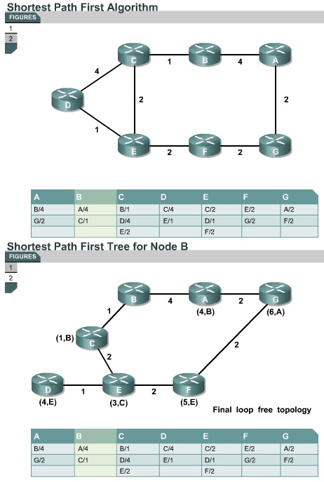
When the databases are complete, each router uses the SPF algorithm to calculate a loop free logical topology to every known network. The shortest path with the lowest cost is used in building this topology, therefore the best route is selected.
Routing information is now maintained. When there is a change in a link-state, routers use a flooding process to notify other routers on the network about the change. The Hello protocol dead interval provides a simple mechanism for determining that an adjacent neighbor is down. -
This page concludes this lesson. The next lesson will explain more about OSPF. The first page will discuss the configuration of OSPF.

Configuring OSPF routing process
2.2.8
This page will teach students how to configure OSPF.
OSPF routing uses the concept of areas. Each router contains a complete database of link-states in a specific area. An area in the OSPF network may be assigned any number from 0 to 65,535. However a single area is assigned the number 0 and is known as area 0. In multi-area OSPF networks, all areas are required to connect to area 0. Area 0 is also called the backbone area.
OSPF configuration requires that the OSPF routing process be enabled on the router with network addresses and area information specified. Network addresses are configured with a wildcard mask and not a subnet mask. The wildcard mask represents the links or host addresses that can be present in this segment. Area IDs can be written as a whole number or dotted decimal notation.
To enable OSPF routing, use the global configuration command syntax:
Router(config)#router ospfprocess-id
The process ID is a number that is used to identify an OSPF routing process on the router. Multiple OSPF processes can be started on the same router. The number can be any value between 1 and 65,535. Most network administrators keep the same process ID throughout an autonomous system, but this is not a requirement. It is rarely necessary to run more than one OSPF process on a router. IP networks are advertised as follows in OSPF:
Router(config-router)#network address wildcard-mask area area-id
Each network must be identified with the area to which it belongs. The network address can be a whole network, a subnet, or the address of the interface. The wildcard mask represents the set of host addresses that the segment supports. This is different than a subnet mask, which is used when configuring IP addresses on interfaces.
The Lab Activity will help students configure and verify OSPF routing.
This next page will teach students how to configure an OSPF loopback interface.

Sunday, December 16, 2012

OSPF Hello protocol

OSPF Hello protocol
2.2.6 This page will introduce hello packets and the Hello protocol.
When a router starts an OSPF routing process on an interface, it sends a hello packet and continues to send hellos at regular intervals. The rules that govern the exchange of OSPF hello packets are called the Hello protocol.
At Layer 3 of the OSI model, the hello packets are addressed to the multicast address 224.0.0.5. This address is “all OSPF routers”. OSPF routers use hello packets to initiate new adjacencies and to ensure that neighbor routers are still functioning. Hellos are sent every 10 seconds by default on broadcast multi-access and point-to-point networks. On interfaces that connect to NBMA networks, such as Frame Relay, the default time is 30 seconds.
On multi-access networks the Hello protocol elects a designated router (DR) and a backup designated router (BDR).
Although the hello packet is small, it consists of the OSPF packet header. For the hello packet the type field is set to 1.
The hello packet carries information that all neighbors must agree upon before an adjacency is formed, and link-state information is exchanged.
The Interactive Media Activity will help students identify the fields in an OSPF packet header.
The next page will describe the OSPF routing process.

OSPF network types

OSPF network types
2.2.5 This page will introduce the three types of OSPF networks.
A neighbor relationship is required for OSPF routers to share routing information. A router will try to become adjacent, or neighbor, to at least one other router on each IP network to which it is connected. OSPF routers determine which routers to become adjacent to based on the type of network they are connected to. Some routers may try to become adjacent to all neighbor routers. Other routers may try to become adjacent to only one or two neighbor routers. Once an adjacency is formed between neighbors, link-state information is exchanged.
OSPF interfaces automatically recognize three types of networks:
  • Broadcast multi-access, such as Ethernet
  • Point-to-point networks
  • Nonbroadcast multi-access (NBMA), such as Frame Relay
A fourth type, point-to-multipoint, can be manually configured on an interface by an administrator. 
In a multi-access network, it is not known in advance how many routers will be connected. In point-to-point networks, only two routers can be connected.
In a broadcast multi-access network segment, many routers may be connected. If every router had to establish full adjacency with every other router and exchange link-state information with every neighbor, there would be too much overhead. If there are 5 routers, 10 adjacency relationships would be needed and 10 link-states sent. If there are 10 routers then 45 adjacencies would be needed. In general, for n routers, n*(n-1)/2 adjacencies would need to be formed.
The solution to this overhead is to hold an election for a designated router (DR). This router becomes adjacent to all other routers in the broadcast segment. All other routers on the segment send their link-state information to the DR. The DR in turn acts as the spokesperson for the segment. The DR sends link-state information to all other routers on the segment using the multicast address of 224.0.0.5 for all OSPF routers.
Despite the gain in efficiency that electing a DR provides, there is a disadvantage. The DR represents a single point of failure. A second router is elected as a backup designated router (BDR) to take over the duties of the DR if it should fail. To ensure that both the DR and the BDR see the link-states all routers send on the segment, the multicast address for all designated routers, 224.0.0.6, is used.
On point-to-point networks only two nodes exist and no DR or BDR is elected. Both routers become fully adjacent with each other.
The Interactive Media Activity will help students recognize the three types of OSPF networks.
The next page will describe the OSPF Hello protocol.

Shortest path algorithm

Shortest path algorithm
2.2.4 This page will explain how OSPF uses the shortest-path algorithm to determine the best path to a destination.
In this algorithm, the best path is the lowest cost path. Edsger Wybe Dijkstra, a Dutch computer scientist, formulated the shortest path-algorithm, also known as Dijkstra's algorithm. The algorithm considers a network to be a set of nodes connected by point-to-point links. Each link has a cost. Each node has a name. Each node has a complete database of all the links and so complete information about the physical topology is known. All router link-state databases, within a given area, are identical. The table in Figure shows the information that node D has received. For example, D received information that it was connected to node C with a link cost of 4 and to node E with a link cost of 1.
The shortest path algorithm then calculates a loop-free topology using the node as the starting point and examining in turn information it has about adjacent nodes. In Figure , node B has calculated the best path to D. The best path to D is by way of node E, which has a cost of 4. This information is converted to a route entry in B which will forward traffic to C. Packets to D from B will flow B to C to E, then to D in this OSPF network.
In the example, node B determined that to get to node F the shortest path has a cost of 5, through node C. All other possible topologies will either have loops or a higher cost paths.
The next page will explain the concept of OSPF networks.

Thursday, December 13, 2012

Comparing OSPF with distance vector routing protocols

Comparing OSPF with distance vector routing protocols
2.2.3 This page will explain how OSPF compares to distance vector protocols such as RIP. Link-state routers maintain a common picture of the network and exchange link information upon initial discovery or network changes. Link-state routers do not broadcast routing tables periodically as distance vector protocols do. Therefore, link-state routers use less bandwidth for routing table maintenance.
RIP is appropriate for small networks, and the best path is based on the lowest number of hops. OSPF is appropriate for large, scalable internetworks, and the best path is determined by the speed of the link. RIP and other distance vector protocols use simple algorithms to compute best paths. The SPF algorithm is complex. Routers that implement distance vector protocols need less memory and less powerful processors than those that implement OSPF.
OSPF selects routes based on cost, which is related to speed. The higher the speed, the lower the OSPF cost of the link.
OSPF selects the fastest loop-free path from the SPF tree as the best path in the network.
OSPF guarantees loop-free routing. Distance vector protocols may cause routing loops.
If links are unstable, flooding of link-state information can lead to unsynchronized link-state advertisements and inconsistent decisions among routers.
OSPF addresses the following issues:
  • Speed of convergence
  • Support for Variable Length Subnet Mask (VLSM)
  • Network size
  • Path selection
  • Grouping of members
In large networks RIP convergence can take several minutes since the routing table of each router is copied and shared with directly connected routers. After initial OSPF convergence, maintaining a converged state is faster because only the changes in the network are flooded to other routers in an area.
OSPF supports VLSMs and therefore is referred to as a classless protocol. RIP v1 does not support VLSMs, however, RIP v2 does support VLSMs.
RIP considers a network that is more than 15 routers away to be unreachable because the number of hops is limited to 15. This limits RIP to small topologies. OSPF has no size limits and is suitable for intermediate to large networks.
RIP selects a path to a network by adding one to the hop count reported by a neighbor. It compares the hop counts to a destination and selects the path with the smallest distance or hops. This algorithm is simple and does not require a powerful router or a lot of memory. RIP does not take into account the available bandwidth in best path determination.
OSPF selects a path using cost, a metric based on bandwidth. All OSPF routers must obtain complete information about the networks of every router to calculate the shortest path. This is a complex algorithm. Therefore, OSPF requires more powerful routers and more memory than RIP.
RIP uses a flat topology. Routers in a RIP region exchange information with all routers. OSPF uses the concept of areas. A network can be subdivided into groups of routers. In this way OSPF can limit traffic to these areas. Changes in one area do not affect performance in other areas. This hierarchical approach allows a network to scale efficiently.
The Interactive Media Activity will help students learn the differences between link-state and distance vector protocols.
The next page will discuss the shortest path algorithm