Wednesday, November 16, 2011

Sequencing numbers

Sequencing numbers 
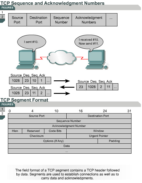
10.1.5 TCP breaks data into segments. After the synchronization process occurs and the window size has been established, the data segments are transported from the sender to the receiver. The data segments must be reassembled after all the data is received. There is no guarantee that the data will arrive in the order it was transmitted. TCP applies sequence numbers to the data segments that are transmitted so that the receiver can reassemble the bytes in their original order. This way, if TCP segments arrive out of order, the segments will still be assembled correctly.
These sequencing numbers also act as reference numbers so that the receiver will know if it has received all of the data. They also identify the missing data pieces to the sender so it can retransmit the missing data. This offers increased efficiency since the sender only needs to resend the missing segments instead of the entire set of data.
Each TCP segment is numbered before transmission. 
The sequence number portion comes after the destination port in the segment format. At the receiving station, TCP uses the sequence numbers to reassemble the segments into a complete message. If a sequence number is missing in the series, that segment is retransmitted.
The next page discusses positive acknowledgments.

Windowing and window size

Windowing and window size 
10.1.4 The amount of data that needs to be transmitted is often too large to be sent in a single data segment. In this case, the data must be broken into smaller pieces to allow for proper data transmission. TCP is responsible for breaking data into segments. This can be compared to the way that small children are fed. Their food is cut into smaller pieces that their mouths can accommodate. Additionally, a device may not be able to receive data as quickly as the source can send it. The device may be busy with other tasks or the sender may be a more robust device.
Once the data is segmented, it must be transmitted to the destination device. One of the services provided by TCP is flow control, which regulates how much data is sent during a given transmission period. The process of flow control is known as windowing.
Window size determines the amount of data that can be transmitted at one time before the destination responds with an acknowledgment. After a host transmits the window-sized number of bytes, the host must receive an acknowledgment that the data has been received before it can send any more data. For example, if the window size is 1, each byte must be acknowledged before the next byte is sent. 
TCP utilizes windowing to dynamically determine transmission size. Devices negotiate a window size to allow a specific number of bytes to be transmitted before an acknowledgment. 
This process of dynamically varying the window size increases reliability. The window size can be varied based upon acknowledgments.
The Interactive Media Activity will help students understand the concept of windowing.
The next page describes TCP sequence numbers.

Denial of service attacks

Denial of service attacks 
10.1.3 his page will teach students about denial of service (DoS) attacks. DoS attacks are designed to deny services to legitimate hosts that try to establish connections. DoS attacks are commonly used by hackers to halt system responses. One type of DoS is known as SYN flooding. SYN flooding exploits the normal three-way handshake and causes targeted devices to acknowledge to source addresses that will not complete the handshake.
The three-way handshake begins when the initiating host sends a SYN packet. The SYN packet includes the source IP address and the destination IP address. This source and destination address information is used by the recipient to send the acknowledgment packet back to the initiating device. 
In a DoS attack, the hacker initiates a SYN but spoofs the source IP address. Spoofing is a term used when the receiving device replies to a non-existent, unreachable IP address and then is placed in a wait state until it receives the final acknowledgment from the initiator. The waiting request is placed in a connection queue or a holding area in memory. This wait state requires the attacked device to use system resources, such as memory, until the connection timer times out. Hackers will flood the attacked host with false SYN requests to utilize all of its connection resources and prevent it from responding to legitimate connection requests.
To defend against these attacks, system administrators may decrease the connection timeout period and increase the connection queue size. Software also exists that can detect these types of attacks and initiate defensive measures.
The next page will discuss the concept of windowing.

Monday, October 31, 2011

Synchronization or three-way handshake

Synchronization or three-way handshake 
10.1.2 This page will explain the synchronization process that TCP uses. The process is also called a three-way handshake.
TCP is a connection-oriented protocol. Prior to data transmission, the two communicating hosts go through a synchronization process to establish a virtual connection for each session between hosts. This synchronization process ensures that both sides are ready for data transmission and allows the devices to determine the initial sequence numbers for that session. This process is known as a three-way handshake. This is a three-step process that establishes the virtual connection between the two devices. It is also important to note that the three-way handshake is initiated by a client host. To establish a TCP session, the client host will use the well-known port number of the service it wishes to contact on a server host.
In step one, the initiating host (client) sends a synchronization (SYN flag set) packet to initiate a connection. This indicates that a packet has a valid initial Sequence Number value in this segment for this session of x. The SYN bit set in the header indicates a connection request. The SYN bit is single bit in the code field of the TCP segment header. The Sequence Number is a 32 bit field TCP segment header.
In step two, the other host receives the packet, records the Sequence Number of x from the client, and replies with an acknowledgment (ACK flag set). The ACK control bit set indicates that the Acknowledgment Number field contains a valid acknowledgment value. The ACK flag is a single bit in the code field of the TCP segment header and the Acknowledgment Number is a 32 bit field TCP segment header. Once a connection is established, the ACK flag is set for all segments during the session. The Acknowledgment Number field contains the next sequence number that this host is expecting to receive (x + 1). The Acknowledgment Number of x + 1 means the host has received all bytes up to and including x, and expects to next receive byte x + 1. The host also initiates a return session. This includes a TCP segment with its own initial Sequence Number value of y and with the SYN flag set.
In step three, the initiating host responds with a simple Acknowledgment Number value of y + 1, which is the Sequence Number value of Host B + 1. This indicates that it received the previous acknowledgment and finalizes the connection process for this session.
It is important to understand that initial sequence numbers are used to initiate communication between two devices. They act as reference starting numbers between the two devices. The sequence numbers give each host a way to acknowledge so that the receiver knows the sender is responding to the proper connection request.
The Interactive Media Activity will help students understand synchronization.
The next page will discuss denial of service attacks

TCP Operation

TCP Operation 
10.1.1This page will explain how the transport layer provides reliability and flow control.
IP addresses allow for the routing of packets between networks. However, IP makes no guarantees about delivery. The transport layer is responsible for the reliable transport of and regulation of data flow from source to destination. This is accomplished through the use of sliding windows and sequencing numbers along with a synchronization process. This process ensures that each host is ready and willing to communicate. 
To understand reliability and flow control, think of a student who studies a foreign language for one year. Now imagine the student visits a country where the language is used. The student must ask people to repeat their words for reliability and to speak slowly for comprehension, which relates to the concept of flow control. The transport layer, which is Layer 4 of the OSI model, uses TCP to provide these services to Layer 5.
The next page will describe the concept of synchronization.

Module 10: Intermediate TCP/IP / Overview


Module 10: Intermediate TCP/IP
Overview

Routers use the IP address information in an IP packet header to determine the interface to which a packet should be switched based on its destination. Since IP does not ensure that the packet reaches the destination, it is described as an unreliable, connectionless protocol, that uses best-effort delivery. If packets are dropped in route, arrive in the wrong order, or are transmitted faster than the receiver can accept them, IP alone cannot correct the problem. To address these problems, IP relies on TCP. This module describes TCP and its functions and introduces UDP, another important Layer 4 protocol.
Each layer within the OSI reference model has various functions. These functions are independent of the other layers. Each layer expects to receive services from the layer beneath it, and each layer provides certain services to the layer above it. The application, presentation, and session layers of the OSI model, which are all considered to be part of the application layer in the TCP/IP model, access the services of the transport layer through logical entities called ports. This module will introduce the concept of ports and will explain the critical importance of ports and port numbers in data networking.
This module covers some of the objectives for the CCNA 640-801, INTRO 640-821, and ICND 640-811 exams. - 
Students who complete this module should be able to perform the following tasks: 
  • Describe TCP and its functions
  • Describe TCP synchronization and flow control
  • Describe UDP operation and processes
  • Identify common port numbers
  • Describe multiple conversations between hosts
  • Identify ports used for services and clients
  • Describe port numbering and well known ports
Understand the differences and the relationship between MAC addresses, IP addresses, and port numbers 

Saturday, October 22, 2011

Module 9: Summary


Summary
The show ip route command is used to gather detailed information about the routes installed on the router. It displays the contents of the IP routing table. New routes may be added with static routing, which allows an administrator to manually define routes, or with dynamic routing, which uses the rules defined by a routing protocol to exchange information and determine the best path.
Default routes are used when the router is unable to match a destination network with a more specific entry in the routing table. The router uses this default route to reach the gateway of last resort in an effort to forward the packet.
The path determination function occurs at the network layer of the OSI model. It enables a router to evaluate the available paths to a destination and to establish the preferred handling of a packet. This information is configured manually or collected dynamically. The administrative distance of the route is used by the router to decide what the best path is to a particular destination. The administrative distance is a number that measures the trustworthiness of the source of the route information. Lower administrative distances indicate more trustworthy sources.
To determine the best route to a destination, routing protocols use a value that measures the desirability of a route called a metric. The metric is usually determined by factors such as hop count, bandwidth, delay, load, reliability, and cost. Typically, the smaller the metric number, the better the path.
Troubleshooting should be an orderly process based on the networking standards set in place by an administrator. Documentation is an important part of the troubleshooting process. Indicator lights are a useful tool for troubleshooting at Layer 1. At Layer 3, ping is used to test network connectivity. Telnet connections are used to verify the application layer software between a source and a destination.
The show interfaces command shows the status of two important portions of the interfaces. They are the physical or hardware portion and logical or software portion. These can be related to the Layer 1 and the Layer 2 functions. If the interface is up and the line protocol is down, a Layer 2 problem exists. If the physical layer is properly functioning, then all other directly connected Cisco devices should be displayed. If no known device appears, a Layer 1 problem likely exists.
To debug connectivity issues, the show cdp neighbors command is used to display information about directly connected neighbors. Use the traceroute command to trace the routes that packets take to destinations. This command can be used to test the network layer at each hop and provide performance benchmarks.
To verify the routing protocol configuration, use the show ip protocols and show ip route commands. These commands display information about routing protocols and the routing table. To determine the type of cable connected without inspecting the cables, use the show controllers command.
The debug command is used to display dynamic data and events. Since the show commands only display static information, they provide a historical picture of the router operation. The debug command output gives more insight to the current events of the router.