Saturday, August 13, 2011

IGRP stability features

IGRP stability features
7.3.4 This page will describe three features that are designed to enhance the stability of IGRP:


• Holddowns
• Split horizons
• Poison reverse updates

Holddowns
Holddowns are used to prevent regular update messages from reinstating a route that may not be up. When a router goes down, neighbor routers detect this from the lack of regularly scheduled update messages.

Split horizons
Split horizons are derived from the premise that it is not useful to send information about a route back in the direction from which it came. The split horizon rule helps prevent routing loops between adjacent routers.

Poison reverse updates
Poison reverse updates are used to prevent larger routing loops. Increases in routing metrics usually indicate routing loops. Poison reverse updates then are sent to remove the route and place it in holddown. With IGRP, poison reverse updates are sent only if a route metric has increased by a factor of 1.1 or greater.

IGRP also maintains many timers and variables that contain time intervals. These include an update timer, an invalid timer, a holddown timer, and a flush timer.

The update timer specifies how frequently routing update messages should be sent. The IGRP default for this variable is 90 seconds.

The invalid timer specifies how long a router should wait in the absence of routing-update messages about a route before it declares that route invalid. The IGRP default for this variable is three times the update period.

The holddown timer specifies the amount of time for which information about poorer routes is ignored. The IGRP default for this variable is three times the update timer period plus 10 seconds.

Finally, the flush timer indicates how much time should pass before a route is flushed from the routing table. The IGRP default is seven times the routing update timer.

IGRP lacks support for VLSM. Cisco has created Enhanced IGRP to correct this problem.

The next page will show students how to configure IGRP.

IGRP routes

IGRP routes
7.3.3 This page will introduce the three types of routes that IGRP advertises:


• Interior
• System
• Exterior

Interior
Interior routes are routes between subnets of a network attached to a router interface. If the network attached to a router is not subnetted, IGRP does not advertise interior routes.

System
System routes are routes to networks within an autonomous system. The Cisco IOS software derives system routes from directly connected network interfaces and system route information provided by other IGRP routers or access servers. System routes do not include subnet information.

Exterior
Exterior routes are routes to networks outside the autonomous system that are considered when a gateway of last resort is identified. The Cisco IOS software chooses a gateway of last resort from the list of exterior routes that IGRP provides. The software uses the gateway of last resort if a better route is not found and the destination is not a connected network. If the autonomous system has more than one connection to an external network, different routers can choose different exterior routers as the gateway of last resort.

The Interactive Media Activity will help students understand the different types of IGRP routes.

The next page will introduce three features that increase the stability of IGRP.

IGRP metrics

IGRP metrics
7.3.2 This page will describe the metrics that IGRP uses.


The show ip protocols command displays parameters, filters, and network information about the routing protocols in use on the router. The algorithm used to calculate the routing metric for IGRP is shown in the graphic. It defines the value of the K1 to K5 metrics and provides information about the maximum hop count. The metric K1 represents bandwidth and the metric K3 represents delay. By default the values of the metrics K1 and K3 are set to 1, and K2, K4, and K5 are set to 0.

This composite metric is more accurate than the hop count metric that RIP uses to choose a path to a destination. The path that has the smallest metric value is the best route.

IGRP uses the following metrics:

• Bandwidth – The lowest bandwidth value in the path
• Delay – The cumulative interface delay along the path
• Reliability – The reliability on the link toward the destination as determined by the exchange of keepalives
• Load – The load on a link toward the destination based on bits per second

IGRP uses a composite metric. This metric is calculated as a function of bandwidth, delay, load, and reliability. By default, only bandwidth and delay are considered. The other parameters are considered only if enabled through configuration. Delay and bandwidth are not measured values, but are set with the delay and bandwidth interface commands. The show ip route command in the example shows the IGRP metric values in brackets. A link with a higher bandwidth will have a lower metric and a route with a lower cumulative delay will have a lower metric.

The next page will discuss the IGRP routes.

IGRP / IGRP features

IGRP
IGRP features
7.3.1 This page will explain the main features and functions of IGRP.


IGRP is a distance vector IGP. Distance vector routing protocols measure distances to mathematically compare routes. This measurement is known as the distance vector. Routers that use distance vector protocols must send all or a portion of their routing table in a routing update message at regular intervals to each neighbor router. As routing information spreads throughout the network, routers perform the following functions:

• Identify new destinations

• Learn of failures

IGRP is a distance vector routing protocol developed by Cisco. IGRP sends routing updates at 90 second intervals. These updates advertise all the networks for a particular AS. Key design characteristics of IGRP are a follows:

• The versatility to automatically handle indefinite, complex topologies
• The flexibility needed to segment with different bandwidth and delay characteristics
• Scalability for functioning in very large networks

By default, the IGRP routing protocol uses bandwidth and delay as metrics. Additionally, IGRP can be configured to use a combination of variables to determine a composite metric. These variables are as follows:

• Bandwidth
• Delay
• Load
• Reliability

The next page will introduce the IGRP metrics.

Integrating static routes with RIP

Integrating static routes with RIP
7.2.10 This page will explain how static routes can be configured on a router that uses RIP.


Static routes are user-defined routes that force packets to take a set path from a source to a destination. Static routes become very important if the Cisco IOS software does not learn a route to a particular destination. They are also used to specify a gateway of last resort, which is commonly referred to as a default route. If a packet is destined for a subnet that is not explicitly listed in the routing table, the packet is forwarded to the default route.

A router that runs RIP can receive a default route through an update from another router that runs RIP. Another option is for the router to generate the default route itself.

Use the no ip route global configuration command to remove static routes. The administrator can override a static route with dynamic routing information by adjusting the administrative distance values. Each dynamic routing protocol has a default administrative distance (AD). A static route can be defined as less desirable than a dynamically learned route, as long as the AD of the static route is higher than that of the dynamic route. Note that after the static route to network 172.16.0.0 through 192.168.14.2 was entered, the routing table does not show it. Only the dynamic route learned through RIP is present. This is because the AD of 130 is higher for the static route, and unless the RIP route through S0/0 goes down, the static route will not be installed in the routing table.

Static routes that point out an interface will be advertised by the RIP router that owns the static route and propagated throughout the internetwork. This is because static routes that point to an interface are considered in the routing table to be connected and thus lose their static nature in the update. If a static route is assigned to an interface that is not defined in a network command, a redistribute static command must be specified in the RIP process before RIP will advertise the route.

When an interface goes down, all static routes pointing out that interface are removed from the IP routing table. Likewise, when the software can no longer find a valid next hop for the address specified in the static route, then the static route is removed from the IP routing table.

In Figure a static route has been configured on the GAD router to take the place of the RIP route in the event that the RIP routing process fails. This is referred to as a floating static route. To configure the floating static route, an AD of 130 was defined on the static route. This is greater than the default AD of RIP, which is 120. The BHM router would also need to be configured with a default route.

The Lab Activity will teach students how to define static routes when RIP is used.

This page concludes this lesson. The next lesson will discuss IGRP. The first page provides an overview of IGRP.

Load balancing across multiple paths

Load balancing across multiple paths
7.2.9 This page will further explain how routers use load balancing to transmit packets to a destination IP address over multiple paths. The paths are derived either statically or with dynamic protocols, such as RIP, EIGRP, OSPF, and IGRP.


When a router learns multiple routes to a specific network, the route with the lowest administrative distance is installed in the routing table. Sometimes the router must select a route from among many, learned through the same routing process with the same administrative distance. In this case, the router chooses the path with the lowest cost or metric to the destination. Each routing process calculates its cost differently and the costs may need to be manually configured in order to achieve load balancing.

If the router receives and installs multiple paths with the same administrative distance and cost to a destination, load-balancing can occur. Cisco IOS imposes a limit of up to six equal cost routes in a routing table, but some IGPs have their own limitations. EIGRP allows up to four equal cost routes.

By default, most IP routing protocols install a maximum of four parallel routes in a routing table. Static routes always install six routes. The exception is BGP, which by default allows only one path to a destination.

The range of maximum paths is one to six paths. To change the maximum number of parallel paths allowed, use the following command in router configuration mode:

Router(config-router)#maximum-paths [number ]

IGRP can load balance up to six unequal links. RIP networks must have the same hop count to load balance, whereas IGRP uses bandwidth to determine how to load balance.

In Figure , there are three ways to reach Network X:

• E to B to A with a metric of 30

• E to C to A with a metric of 20

• E to D to A with a metric of 45

Router E chooses the second path, E to C to A with a metric of 20, since it is a lower cost than 30 and 45.

Cisco IOS supports two methods of load balancing for IP packets. These are per-packet and per-destination load balancing. If process switching is enabled, the router will alternate paths on a per-packet basis. If fast switching is enabled, only one alternate route will be cached for the destination address. All packets that are bound for a specific host will take the same path. Packets bound for a different host on the same network may use an alternate route. Traffic is load balanced on a per-destination basis.

By default the router uses per-destination load balancing, also called fast switching. The route cache allows outgoing packets to be load-balanced on a per-destination basis rather than on a per-packet basis. To disable fast switching, use the no ip route-cache command. Using this command will cause traffic to be load balanced on a per-packet basis.

In the Lab Activities, students will configure and observe load balancing.

The next page will discuss static routes with RIP.

Load balancing with RIP

Load balancing with RIP
7.2.8 This page will describe load balancing and explain how RIP uses this feature.


Load balancing is a concept that allows a router to take advantage of multiple best paths to a given destination. These paths are either statically defined by a network administrator or calculated by a dynamic routing protocol such as RIP.

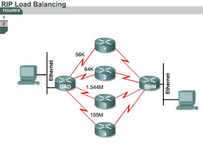
RIP is capable of load balancing over as many as six equal-cost paths. The default is four paths. RIP performs what is referred to as “round robin” load balancing. This means that RIP takes turns forwarding packets over the parallel paths.

Figure shows an example of RIP routes with four equal cost paths. The router will start with an interface pointer to the interface connected to Router 1. Then the interface pointer cycles through the interfaces and routes in a deterministic fashion such as 1-2-3-4-1-2-3-4-1 and so on. Since the metric for RIP is hop count, the speed of the links is not considered. Therefore, the 56-Kbps path will be given the same preference as the 155-Mbps path.

The show ip route command can be used to find equal cost routes. For example, Figure is a display of the output show ip route to a particular subnet with multiple routes.

Notice there are two routing descriptor blocks. Each block is one route. There is also an asterisk (*) next to one of the block entries. This corresponds to the active route that is used for new traffic.

The next page will explain load balancing in greater detail.