Saturday, October 22, 2011

Layer 1 troubleshooting using indicators / Layer 3 troubleshooting using ping


Layer 1 troubleshooting using indicators
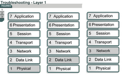
9.2.4 The page will explain how to troubleshoot Layer 1 issues with the help of indicator lights. Most interfaces or NICs have indicator lights that show if there is a valid connection. This light is often called the link light. The interface may also have lights to indicate when traffic is transmitted (TX) or received (RX). If the interface has indicator lights that do not show a valid connection, check for faulty or incorrect cabling. If cabling is correct, power off the device and reseat the interface card.
Check to make sure that all cables are connected to the appropriate ports. Make sure that all cross-connects are properly patched to the correct location using the appropriate cable and method. 
Verify that the proper cable is used. A crossover cable may be required for direct connections between two switches or hubs, or between two hosts such as PCs or routers. Verify that the cable from the source interface is properly connected and is in good condition. If there is doubt that the connection is good, reseat the cable and ensure that the connection is secure. Try replacing the cable with a known working cable. If this cable connects to a wall jack, use a cable tester to ensure that the jack is properly wired.
Also check any transceiver in use to ensure that it is the correct type, is properly connected, and is properly configured. If the problem continues after the cable is replaced, replace the transceiver if one is used.
Always check to make sure that the device is powered on. Always check the basics before running diagnostics or attempting complex troubleshooting. 
The next page will describe the ping command.
Layer 3 troubleshooting using ping 
9.2.5 
This page will explain how the ping utility can be used to test network connectivity. Many network protocols support an echo protocol to help diagnose basic network connectivity. Echo protocols are used to determine if protocol packets are routed. The ping command sends a packet to the destination host and then waits for a reply packet from that host. Results from this echo protocol can help evaluate the path-to-host reliability, delays over the path, and whether the host can be reached or is functioning. The ping output displays the minimum, average, and maximum times it takes for a ping packet to find a specified system and return. The ping command uses ICMP to verify the hardware connection and the logical address of the network layer. This is a very basic way to test network connectivity. Figure shows the ICMP message types. This is a very basic testing mechanism for network connectivity.
In Figure , the ping target 172.16.1.5 responded successfully to all five datagrams sent. Each exclamation point (!) indicates a successful echo. One or more periods (.) indicates that the application on the router timed out before it received a packet echo from the ping target.
The following command activates a diagnostic tool that is used to test connectivity:
Router#ping [protocol] {host | address}
To test network connectivity, the ping command sends ICMP echo requests to a target host and measures how long it takes to reply. The ping command tracks the number of packets sent, the number of replies received, and the percentage of packets lost. It also tracks the amount of time required for packets to reach the destination and for replies to be received. This information can be used to verify communications between hosts and determine if information was lost. 
The ping command can be invoked from both user EXEC mode and privileged EXEC mode. The ping command can be used to confirm basic network connectivity on AppleTalk, ISO Connectionless Network Service (CLNS), IP, Novell, Apollo, VINES, DECnet, or XNS networks.
The use of an extended ping command directs the router to perform a more extensive range of test options. To use extended ping, type ping at the command line, and press the Enter key. Prompts will appear each time the Enter key is pressed. These prompts provide many more options than with a standard ping
Use the ping command when the network functions properly to see how the command works under normal conditions. This can be used as a comparison, or baseline, when troubleshooting.
The Lab Activity will allow students to use the ping command to send an ICMP echo request.
The next page will describe the Telnet application.

Testing by OSI layers

Testing by OSI layers
9.2.3 This page will describe the types of errors that occur at the first three layers of the OSI model.
Layer 1 errors can include the following: 
  • Broken cables
  • Disconnected cables
  • Cables connected to the wrong ports
  • Intermittent cable connection
  • Rollover, crossover, or straight-through cables used incorrectly
  • Transceiver problems
  • DCE cable problems
  • DTE cable problems
  • Devices turned off
Layer 2 errors can include the following: 
  • Improperly configured serial interfaces
  • Improperly configured Ethernet interfaces
  • Improper encapsulation set
  • Improper clockrate settings on serial interfaces
  • Network interface card (NIC) problems
Layer 3 errors can include the following: 
  • Routing protocol not enabled
  • Wrong routing protocol enabled
  • Incorrect IP addresses
  • Incorrect subnet masks
If errors appear on the network, the process of testing through the OSI layers should begin. The ping command is used at Layer 3 to test connectivity. At Layer 7 the telnet command may be used to verify the application layer software between source and destination stations. Both of these commands will be discussed in detail in a later section.
The next page will explain how indicator lights can be used to test a network.

Using a structured approach to troubleshooting

Using a structured approach to troubleshooting 
9.2.2 Troubleshooting is a process that allows a user to find problems on a network. This page explains why an orderly process should be used to troubleshoot a network. This process should be based on the networking standards set in place by a network administrator. Documentation is a very important part of the troubleshooting process. 
The steps in this model are as follows:
Step 1 Collect all available information and analyze the symptoms of the failure.
Step 2 Localize the problem to a particular network segment, module, unit, or user.
Step 3 Isolate the trouble to specific hardware or software within the unit, module, or user network account.
Step 4 Locate and correct the problem.
Step 5 Verify that the problem has been solved.
Step 6 Document the problem and the solution.
Another approach to troubleshooting. These are not the only ways to troubleshoot a network. However, an orderly process is important to keep a network running smoothly and efficiently.
When a structured approach is used, every member of a network support team knows which steps the other team members have completed to troubleshoot the network. If a variety of troubleshooting ideas are tried with no organization or documentation, problem solving is not efficient. Even if a problem is solved in the non-structured environment, it will be difficult to replicate the solution for similar problems.
The Interactive Media Activity will help students become familiar with the troubleshooting process.
The next page will teach students the types of errors that occur at the first three layers of the OSI model.

Network Testing / Introduction to network testing

Network Testing
>Introduction to network testing
9.2.1 This page will give students an overview of how to test a network.
Basic testing of a network should proceed in sequence from one OSI reference model layer to the next. Begin with Layer 1 and work up to Layer 7, if necessary. At Layer 1, look for simple problems such as power cords plugged in the wall and other physical connections. The most common problems that occur on IP networks result from errors in the addressing scheme. It is important to test the address configuration before continuing with further configuration steps.
Each test presented in this lesson focuses on network operations at a specific layer of the OSI model. At Layer 3, the commands telnet and ping are used to test the network.
The next page will discuss the troubleshooting process.

Observing multiple paths to destination

Observing multiple paths to destination 
9.1.9 Multi-path algorithms permit traffic over multiple lines, provide better throughput, and are more reliable than single path algorithms.
IGRP supports unequal cost path load balancing, which is known as variance. The variance command instructs the router to include routes with a metric less than n times the minimum metric route for that destination, where n is the number specified by the variance command. The variable n can take a value between 1 and 128, with the default being 1, which means equal cost load balancing.
rt1 has two routes to network 192.168.30.0. The variance command will be set on rt1 to ensure that both paths to network 192.168.30.0 are utilized.
Figure shows the output from show ip route from rt1 before the variance is configured. FastEthernet 0/0 is the only route to 192.168.30.0. This route has an Administrative Distance of 100 and a metric of 8986.
Figure shows the output from show ip route from rt1 after the variance is configured. The preferred route is interface FastEthernet 0/0, but Serial 0/0 will also be used. After the variance command is executed, IGRP will use load balancing between the two links. 
This page concludes this lesson. The next lesson will discuss network testing. The lesson begins with an overview.

Determining the route next hop / Determining the last routing update

Determining the route next hop
9.1.7 Routing algorithms fill routing tables with a variety of information. Destination next hop associations determine the best path and which router to forward the packet to next. This router represents the next hop on the way to the final destination. 
When a router receives an incoming packet, it checks the destination address and attempts to associate this address with a next hop. 
Determining the last routing update 
9.1.8 
  • show ip route 
  • show ip route address 
  • show ip protocols 
  • show ip rip database 

Determining the route metric

Determining the route metric 
9.1.6 Routing protocols use metrics to determine the best route to a destination. The metric is a value that measures the desirability of a route. Some routing protocols use only one factor to calculate a metric. For example, RIP v1 uses hop count as the only factor to determine the metric of a route. Other protocols base their metric on hop count, bandwidth, delay, load, reliability, and cost. 
Each routing algorithm interprets what is best in its own way. The algorithm generates a number, called the metric value, for each path through the network. A lower metric number generally indicates a better path.
Factors such as bandwidth and delay are static because they remain the same for each interface until the router is reconfigured or the network is redesigned. Factors such as load and reliability are dynamic because they are calculated for each interface in real-time by the router.  
The more factors that make up a metric, the greater the flexibility to tailor network operations to meet specific needs. By default, IGRP uses the static factors bandwidth and delay to calculate a metric value. These two factors can be configured manually to control which routes a router chooses. IGRP may also be configured to include the dynamic factors of load and reliability in the metric calculation. By using dynamic factors, IGRP routers can make decisions based on current conditions. If a link becomes heavily loaded or unreliable, IGRP will increase the metric of routes using that link. An alternate route with a lower metric would be used instead.
IGRP calculates the metric by adding the weighted values of different characteristics of the link to the network in question. Here is the formula for calculating the composite metric for IGRP:
Metric = [K1 * Bandwidth + (K2 * Bandwidth)/(256-load) + K3*Delay] * [K5/(reliability + K4)]
The default constant values are K1 = K3 = 1 and K2 = K4 = K5 = 0.
If K5 = 0, the [K5/(reliability + K4)] term is not used. Given the default values for K1 through K5, the composite metric calculation used by IGRP reduces to Metric = Bandwidth + Delay.
The Interactive Media Activity will help students understand route metrics.
The next page explains how a next hop is chosen.